Rock Mechanics and Engineering Geology in the design of underground worksE.H. Davis Memorial Lecture
This article has been written as the basis for presentation of the 1993 E.H. Davis Memorial Lecture. After the usual soul searching that goes with such a presentation it was decided to:
- restrict the article to my involvement in the design and construction of underground structures;
- prepare an article which is essentially personal (hence the frequent use from this point on of the first person);
- document key ideas which I have gathered from various people and projects over the years and which have influenced the design and construction of underground works.
I have attempted to prepare an article which can provide the basis for an entertaining lecture at the same time as providing some long term reference value. Also, I have wanted to highlight the role proper geological understanding plays in successful geotechnical engineering. The article is therefore divided into three distinct parts, as follows:
Part 1 Applications and Limitations of Rock Mechanics – The Particular Problem of Underground Excavations in Near Horizontally Bedded Sedimentary Rocks
Part 2 Notes on Geotechnical Models for Underground Works
Part 3 A Thumbnail Engineering Geology of the Triassic Rocks of the Sydney Area
The general idea of the above subdivisions is that they grade from a personal overview in Part 1 to specific local information in Part 3. In many ways this represents my belief that, as a now relatively mature branch of engineering, developments in geotechnical engineering should be related to specific geological regions and units.
Many of the references in this article are taken from the book Comprehensive Rock Engineering published in mid-1993 in 5 volumes. This is an excellent publication and should be the starting point for most future work in the field.
Part 1:
The particular problem of underground excavations in near horizontally bedded sedimentary rocks
1. Introduction
It has transpired that a major proportion of the work I have done in tunnelling has related to near horizontally bedded sedimentary strata, namely:
- the Karoo sediments of Southern Africa
- the Triassic and Permian strata of the Sydney Basin
- Cretaceous mudstones of Central and Northern Queensland
These rocks are not very strong, ranging from 40-80 MPa for the Karoo materials to 15-40 MPa for the Sydney Basin to <5 MPa for the Cretaceous mudstones. A common feature is that in all cases the natural horizontal stresses are greater than overburden pressure.
A number of ideas have come together in relation to tunnelling in these materials over the years, and in this Part I will attempt to trace the development of these ideas in historical sequence. However, before starting I must note that over the years I have found Lauffer’s (1958) categorisation of support loading invaluable in sorting out my ideas. Lauffer’s concept is that support loading should be considered under three categories:
- Loosening Pressure Pressure caused by the weight of blocks or prisms ofloosened or potentially loosened rock in the roof or sidewalls of a tunnel.
- Swelling Pressure Caused by volumetric increases of clays, claystones or other rocks due to exposure to the atmosphere under altered stress conditions.
- True Rock Pressure Pressure on support occurring when the compressive stresses generated in the rock in zones around the tunnel are sufficient to cause failure. Such failure usually commences around the perimeter of the tunnel but may occur within the rock mass on a weak plane such as a gouge filled fault.
2. Historical Development of Ideas Relating to Large Span Openings in Horizontally Bedded Rock
2.1 Early Days
My first serious encounter with tunnelling in rock was when I joined the Rock Mechanics Research Group headed by Dr. Dick Bieniawski at the CSIR in Pretoria. At that time the CSIR had substantial expertise in rock material testing and had played an important role in preparation of early ISRM testing documents. Also, the team was completing what, to me, remains one of the more remarkable testing programmes conducted in rock mechanics. This largely unsung work was the insitu measurement of the complete stress-strain curves of coal pillars with width to height ratios of up to 3.4 (Van Reerden, 1974). I include some of the data here in Figures 1.1 and 1.2, not because they are of any great relevance to the main themes of this article, but because:
- the test work taught me not to be scared of taking on large scale field investigation programmes;
- the results fixed in my mind forever the substantial strength of fractured rock in the post-peak region;
- the results are amongst the most graphic illustrations of the redistribution of stress from failed regions into unfailed regions which I have seen;
- the New Largo Colliery where the last tests were completed was my first encounter with large span, flat roofed tunnels.
It was in discussing flat roofed tunnels with Bieniawski that I was first introduced to the linear arch concept which was published by Evans in 1940 and which is illustrated in Figure 1.3. We shall return to this linear arch concept in some detail later in the story (Sections 2.3 and 2.4).
I had always been interested in large underground hydroelectric power caverns and a paper which had a major impact on my subsequent thinking was that describing the Poatina Hydroelectric Scheme in Tasmania. This classic by Endersbee & Rotto (1963) introduced two concepts to deal with relatively high horizontal stresses in horizontally bedded sandstone.
The first concept was the use of a flat-topped cavern as opposed to the traditional arch (see Figure 1.4). This was based on stress analyses and simple logic which indicated that there was little purpose in cutting an arch into beds of sandstone which would act as flat plates spanning the excavation.
The second concept was the use of stress relieving slots which were created by drilling closely spaced holes into the haunches of the cavern roof. Wooden dowels were inserted into these holes so as to create a compressible medium in the slot. The idea of these slots was to relieve the high stress concentrations generated at the haunches as a result of forming a cavern in a relatively high horizontal stress field.
The paper on Poatina fascinated me because at that time the idea that the major principal stresses in most near surface rocks was actually horizontal and not vertical was quite new. Most, if not all, tunnel design work was based on the idea that the dominant loading was due to gravitational effects (i.e. the weight of loosened material above the opening). Furthermore, the geometric design of the Poatina cavern involved similar principles to those I had been taught in mechanical engineering at university. This contrasted quite strongly with much of what was then touted as tunnel design, which to me did not seem to constitute design at all, but rather a process of trial and error during construction.
In 1974 design work commenced on the 1000 MW Drakensberg pump storage scheme which involved a massive underground cavern in horizontally bedded sandstones. Largely because of the fact that at one time in the dim and distant past Tasmania was not too far from the southern part of Africa, the rocks within which the Drakensberg cavern was to be excavated are similar to those at Poatina. Alternative shapes were considered as shown in Figure 1.5. These alternatives included a flat topped Poatina style cavern, an “egg” shape as used in the Waldeck Power Station in Germany, and a new concept of creating an underground cavern which consisted of circular silos for the turbines, connected across the top with a flat topped tunnel.
Two dimensional stress analyses could be done for the Poatina and the Waldeck shapes but it was necessary to undertake 3D finite element analyses to study the concept of circular silos connected with an overhead tunnel. Figures 1.6 and 1.7 show some of the results of the analyses. The obvious became clear, namely that circular silos in horizontally bedded sandstone in a high horizontal stress field provided a very good geometric solution. In particular tensile stress in the sidewalls disappear and the stress concentrations in the crown and floor of the cavern are reduced compared with conventional ‘box’ style chambers.
Subsequent to my work on the caverns there were further design changes made by the prime consultants and I lost track of the project when I moved to Australia. However, the final cavern did include the main concepts which had originally come from a combination of the Paotina work and the idea of using silos for containing each of the turbines and generators. During my period at the CSIR I was responsible for the Tunnelling Research Group and therefore spent some time trying to discover what constituted tunnel design. I found this to be a very frustrating exercise because what was described in the literature and by practitioners as tunnel design did not gel with my training in civil engineering. As far as I could see there were no design methods for tunnels which corresponded to the analytical techniques used in structural engineering, hydraulics and even soil mechanics. Reluctantly, over the years, I have come to realise that this is a fact of life and that tunnel design is different. It is an intimate blend of engineering geology, precedent, structural analysis and the observational method during construction. Geology drives this process and design is only completed when construction is completed.
However, I did realise that there was substantial value to be gained in:
- the use of elastic analyses to study stress concentrations around alternative cavern or tunnel shapes in relation to the likely lateral stress field and geological structure;
- carefully considering the location of the cavern or tunnel in relation to difficult geological features and, where possible, changing the location so as to avoid these difficult features.
I also reached one negative conclusion during this period which relates to the use of complex non-linear finite element techniques.
At that time the power of the finite element method was becoming apparent and many groups throughout the world were developing packages which could, in theory, analyse very complex, non linear material and geological structural properties. These packages included complex joint elements and complex material parameters and it appeared at that stage that a tool would be available which engineers could use to design tunnels in the same sense as they design structures. I spent at least two years trying to apply complex finite element packages to the design of a particular tunnel in a jointed basalt (Ermelo Rail Tunnel on the Richards Bay Line). At the end of this period I came to the conclusion that because it was impossible to know the locations of all defects in advance of tunnelling, and in addition it was impossible to include all defects in a finite element model, one could get any answer one liked with regard to likely support loadings. Further-more, there was one unknown which dominated the solution and that was the delay between the advance of the tunnel face and installation of the support.
There are specific cases where jointed finite element analyses are very valuable in designing underground structures. Two such cases, the Bondi Pumping Chamber and the Sydney Opera House Parking Station, are discussed in Section 2.4.1 below. However, in most cases which relate to long tunnels, there is little value in undertaking anything other than linear elastic (isotropic or anisotropic) analyses.
2.2 Some Research Work
In 1975 I joined Ted Davis’s group at Sydney University. Before I got embroiled in research on socketed piles I did some further analytical work in the stress concentrations around underground openings in horizontally bedded strata. This work was prompted by the worldwide realisation that in most near surface rocks natural horizontal stresses are greater than overburden pressure.
A series of finite element studies was undertaken to prepare parametric solutions for the stress concentrations around different shaped openings in horizontally bedded strata. The technique was to use cross-anisotropic elastic theory and the results were presented in the Wellington ANZ Soils Conference (Pells 1982). They are reproduced here in Figures 1.8 and 1.9. Some further analytical work in this regard was done a few years ago by modelling discrete horizontal bedding defects close to the roof or floor of a circular tunnel. The results are summarised in Figure 1.10 and show that low strength bedding defects have an even greater effect on concentrating stresses than a strongly cross anisotropic material.
These theoretical studies showed that horizontal defects in a relatively high horizontal stress field have a major impact on the level of stress concentration around a tunnel and explained why spalling in the roof and invert of tunnels occurred where normal elastic stress analyses would suggest that the concentrated stresses were less than the material strength. This problem was best illustrated some years later in the Boomerang Tunnel north of Sydney which is discussed in Section 2.4.2. During this period theoretical work was also conducted on the use of elastic solutions to interpreted tunnel convergence and extensometer data to calculate insitu modulus and virgin stress field values. The technique is presented in Pells, McMahon & Redman (1981) and Figure 2.4 illustrates application of the method to data from Thompson Dam.
This very useful tool is based on the simple fact that the radial displacement at any point around an opening being advanced in an isotropic, homogeneous elastic medium is given by an equation (1.1) of the form:
where
= displacement influence factor which is a function of positions and (ratio of horizontal to vertical field stresses)
= a tunnel dimension (say width)
= vertical stress (overburden pressure)
= radial displacement
The general equation given above means that for a particular tunnel of known size and under a known overburden the radial displacement at any point on the perimeter or within the rock mass is given by an equation (1.2) of the form:
where
= known displacement
= known values, being a function of and
= unknown modulus and ratio of horizontal to vertical stress
We have one equation with two unknowns, but every other measurement of radial displacement gives us another equation and therefore a normal tunnel monitoring programme using convergence and extensometer data gives a large amount of redundant data. This information can be readily treated graphically to produce a reasonable interpretation as to the likely insitu mass modulus value and the natural stress field. The following simple example taken from Pells, McMahon and Redman (1980) should serve to clarify the method.
Consider that measurements of tunnel wall displacements have been made at three points around a circular tunnel, namely at 50˚, 80˚ and 160˚ from the horizontal (measured anti-clockwise). Suppose the overburden pressure is 5 MPa and Poisson’s Ratio is 0.3. Suppose the corrected measured radial displacements are 2.36mm, 1.36mm and 3.29mm. For a circular tunnel equation 1.1 becomes (1.3):
where = angle measured anti-clockwise from horizontal
Therefore, from the three measurements we can get three equations, namely:
The equation is best treated graphically as shown in Figure 1.11 because such graphical treatment has the advantage that ill conditioned pairs of equations are readily identified.
2.3 Early Consulting Work in Sydney
Sandy Hollow Tunnel
After departing Sydney University in early 1980 I rejoined the consulting industry and one of the first projects I was involved in was the completion of the Sandy Hollow Tunnel on the Ulan Line. Construction had commenced on this tunnel prior to World War II but work had been abandoned on the whole project, partly due to the great difficulties in tunnelling. SMEC were the prime consultants for the project and my involvement was on behalf of the contractor only a week or so before he was removed from the project.
The tunnel was an amazing sight. It was partly excavated through horizontal coal measure rocks, which included significant thin claystone bands within the poor quality coal seams. Excavation was being undertaken on a heading and bench basis and support was entirely by steel sets, which were first installed in the heading and then extended down to the floor when the bench was removed. As a result of substantial horizontal stresses, heaving and buckling had occurred in the floor and steel sets had been distorted like spaghetti. At that stage it was a classic example of old-fashioned, or pre-NATM, tunnelling and was a contractual disaster. SMEC had the responsibility of sorting out the mess, and since my client was removed from the job I had no further involvement. But the lessons of Sandy Hollow were branded in my memory, riamely:
- Low shear strength, near horizontal defects can cause massive stress concentrations where the natural horizontal stress is the major principal stress.
- The stress concentrations described above can lead to the development of shear failure and buckling in the crown and floor of a tunnel under relatively low cover (i.e. in a situation where one would not normally expect the development of true rock pressure).
- Steel sets with intermittent timber blocking and timber lagging provide a very poor means of primary support for true rock pressure.
- Shear failure and buckling in the invert can be as important as crown failure because, in combina-tion with vehicle traffic and the collection of water, there can be rapid degradation of the invert.
Elura Mine
In 1980 and early 1981 I was involved, together with Barry McMahon, in the design of the open stopes for the new Elura Mine near Cobar. Figure 1.12 shows the concept that was being considered for Elura at that stage and it can be seen that we proposed wide span openings with a thin crown pillar (less than 5m). The analytical work for this design was based on 2D elastic finite element analysis and on the original linear arch studies which were published by Evans (1940). Evans’ work had been drawn to my attention by Bieniawski and I had always viewed with some disbelief the conclusion that very large spans could be sustained under a linear arch of only 3 to 5m in thickness. However, all the analytical work we did for Elura supported this concept, although my involvement with the project ended before it was proved in practice, and I had to wait for completion of the Opera House Car Park to provide a definitive proof of the validity of the theory.
Monasavu Hydro-Electric Scheme, Fiji
The lessons from the 40° inclined penstock tunnel at Monasavu are peripheral to the general theme of tunnels in bedded rock with relatively high horizontal stress, but are nevertheless so important that they must be touched on briefly.
Figure 1.13 shows a cross section through the tunnel system feeding the hydropower station. The problems largely related to the 40° inclined pressure tunnel which was excavated from the bottom up using drill-and-blast in conjunction with an Alimak route climber. This inclined tunnel was a contractual disaster due, in my opinion, to three matters of design philosophy. These were:
- An inclined penstock tunnel was adopted rather than a surface penstock because surface mapping indicated significant areas of slope instability. Yet relatively little subsurface investigation drilling was completed to check whether the below-surface geotechnical problems were significantly less than the obvious areas of surficial instability. In other words, it was the oft-repeated mistake of assuming that problems would somehow disappear by “putting it underground”.
- Water flow requirements only necessitated a small diameter tunnel – hence the adoption of 1.8m. However, excavating an 800m long small diameter tunnel at 40° upwards from the end of an approximately 1 km tailrace tunnel is a nightmare simply because of space restrictions. Ventilation, support installation, survey, illumination, communications and mapping were all very very difficult. I think the Monasavu penstock was the most horrific engineering excavation I have ever been in and this was substantially due to its small diameter.
- A 40° inclined penstock is really neither a tunnel nor a shaft. From the human psychology viewpoint (i.e. when one is in it) it feels near vertical and hence like a shaft. However, from the viewpoint of support and muck handling it is more like a tunnel.
My conclusions from Monasavu were therefore:
- For long tunnels a minimum diameter should be about 2.5m to 2.8m.
- Avoid steep inclined tunnels (say 35° to 60°).
- Don’t make the mistake of thinking that obvious surface geotechnical problems will disappear by adopting a tunnel.
- It takes a substantial quantity of drilling to adequately delineate the geological model in geological environments which involve igneous rocks and a complex tectonic history.
2.4 The Last Decade 1983 to 1993
This period represented my most active association with the tunnelling industry, as it involved over a dozen tunnelling projects, including the following:
- Sydney Ocean Outfall Tunnels and North Head, Malabar and Bondi
- Bondi Pumping Chamber
- Sydney Harbour Tunnel
- Boomerang Creek Tunnel at Mangrove Creek Dam
- Sydney Opera House Parking Station
Also during this period I had substantial involvement with a number of deep excavations in the Sydney CBD and monitoring of these gave data of relevance to tunnel design.
The above projects have all been described in previous publications and it is not appropriate to repeat all the information here. Rather, I simply wish to highlight facets from the projects which were critical to their design and construction and which, I trust, are of value to engineers involved in underground excavations in similar geological strata. These facets are really a continuation of those discussed above inasmuch as they relate to:
- design and construction of wide span caverns in horizontally bedded strata and
- compressive failure in the crown and invert under high horizontal stresses.
2.4.1 Wide Span Caverns
Figure 1.14 shows a cross section through the Bondi Pumping Chamber. It can be seen that the roof material for this chamber comprised an approximately 3m thick bed of sandstone sandwiched between two laminite layers. The initial design for the chamber included a traditional arched roof. When I was asked to review the design it was immediately obvious that the experiences from Poatina and Drakensberg should be brought into play and that the geometry of the cavern roof should be in sympathy with the geological structure and stress field.
Because the Bondi Pumping Chamber is close to the coastal cliffiine it was reasonable to expect that the horizontal stresses are quite low. Therefore, the roof shape was controlled entirely by the geological structure and it was clear to us that the rock would “want” to break to a rectangular shape and that it would be difficult to form a traditional arch. It was also obvious that the geological situation created a near-perfect Evans linear arch inasmuch as the sandstone bed would separate from the underlying and overlying laminite layers.
The design was therefore developed on the basis of a flat roof spanning 12.5m, with the overlying strata being carried by a 2.5m to 4.5m thick linear arch of sandstone. However, the actual sandstone unit contained two bedding horizons and therefore it was necessary to design a reinforcing system which would tie the beds together. The design is described in some detail in Pells & Best (1991).
At that time we had no analytical method of quantifying the density and lengths of the dowels which were necessary to tie together the discrete beds within the 3m sandstone linear arch. Bolt spacing was therefore based on precedent and comprised 24mm diameter full column cement grouted bolts at approximately 1.2m centres in a square pattern. The bolts were 3.9m long, not because of our design requirements but because of existing contractual arrangements.
The roof was created by opening up the span from a central crown drive. A prediction was made of the centreline roof sag as a function of increasing span (see Figure 1.15). Field monitoring of actual roof sag was then used to check whether or not the sandstone unit was acting as a nominal 3m thick linear arch and that therefore the dowels were successfully pinning the discrete beds together and forcing composite behaviour.
Deflection measurements commenced when a 4m central heading was completed and showed that sag ranged between 4mm and 10mm as the span was increased from 4m to 12.5m. The theoretical prediction (see Figure 1.15) was 15mm to 25mm, which suggests the following possibilities:
- The dead weight surcharge on the sandstone layer was lower than assumed in the design.
- The sandstone stiffness was greater than the assumed value of 500 MPa.
- The horizontal stress field was greater than assumed.
The Bondi pumping station provided the launching platform for the wide spans under very shallow cover required for the Sydney Opera House (Bennelong Point) parking station. If it were not for the monitoring results at Bondi we would not have had the confidence to proceed with the Bennelong design because, as illustrated by Figure 1.16, the Bennelong cavern has possibly the greatest span to rock cover ratio of any underground rock cavern.
The design, construction and monitoring of the cavern has been described in detail in several recent articles and papers (The Earthmover, July 1992; Pells, Poulos & Best, 1991; Pells & Best, 1993 and Pells, Mikula & Parker, 1993) and only key points in relation to large spans under shallow cover are canvassed here.
The key concept is the recognition that openings of at least 20m can be spanned by a horizon of Class III, or better, sandstone about 6m thick, provided the horizon can be made to act as a single unit, albeit composed of a material with no tensile strength. The justification for this concept is an extension of linear arch theory, termed “cracked beam model”, which is discussed further below.
The first point to note is that because most interest has been directed to the main cavern, sight has been lost of the fact that 16 other tunnels were required for the project, ranging in span from 2m to 12m (see Figure 1.17) and some of these involved very high span to cover ratios. In particular, the main vehicle entry and exit tunnels, which provided the only access for cavern excavation, involved spans of up to 9m with rock cover as little as 2.2m (see Figure 1.18). In places the rock dowels penetrated the overlying thin soil cover! These initial tunnels were very important in boosting the confidence of all parties (owner, engineers and construction workers) in regard to the safety of the structure.
This brings me to a short aside, but one which is critical to successful underground works. If the construction personnel feel safe and are comfortable with the construction techniques and primary support directed by the engineers, then the project has a good chance of success. If they don’t feel that their safety is being properly addressed, no amount of clever rock mechanics will retrieve the situation. Therefore, it is always worthwhile to commence a project with a conservative level of support and to then allow the construction personnel to be part of decisions to reduce support quantum.
The second point is to emphasise that techniques were developed during the design phase of Bennelong which allowed systematic design of the internal rock reinforcement required to make the multiple sandstone beds which occurred in the roof strata act as a single pseudo-elastic linear arch. It was not necessary to use guess-and-precedent as had to be done at Bondi. The two key techniques are summarised below.
Linear Arch/Cracked Beam Theory
Evan’s linear arch theory was extended by Professor John Booker of Sydney University and incorporated in software written by Coffey Partners International. This model does not require the assumption of a “line of thrust” in the roof beam as in Evan’s original work. Instead, the computer model consists of a series of beam/column segments. Each segment is connected to its neighbour by a joint which is incapable of carrying tension. A one dimensional finite element formulation is used to analyse the complete roof beam. A starting solution is obtained by assuming the intact behaviour. The stress distribution at the interfaces between adjacent beam segments is then calculated and checked for tensile stresses. Where tensile stresses are computed a revised beam section is developed. The deflections are used to modify the alignment of the beam/column segments and the deformation and stress field re-calculated. The process is repeated until convergence is obtained. This usually takes about five cycles where significant tensile cracking occurs. The model gives three main output items:
- centre span deflection;
- extent of cracked zones;
- maximum compressive stress in the rock.
The model allows rapid sensitivity studies of:
- span;
- end constraint conditions;
- initial horizontal stresses;
- rock mass modulus;
- surcharge.
Figure 1.19 shows the results of calculated deflection versus span for a 5m roof beam (E = 1500 MPa) and a uniform surcharge of 200 kPa (which includes self weight). Figure 1.20 gives an alternative method of presentation and shows calculated roof deflection for a 12m span as a function of proximity to collapse load and beam thickness for a triangular surcharge. This was the geometric situation relevant to the Bondi pumping chamber and the Figure also shows the operating load range which was expected at Bondi and the deflection levels at which compressive failure could be expected in the beam.
Cracked beam theory is very useful in conceptualising a design and in providing predictions of likely roof sag. However, the theory has significant limitations. It takes no account of shear failure, either along horizontal weaknesses or diagonally near the supports. It also provides no help in quantifying the reinforce-ment required to make a multi-bedded horizon act as a single unit.
Design of Roof Reinforcement
A single reinforcing element across a joint acts to increase the shear resistance of the joint by the following mechanisms:
- an increase in shear resistance due to the lateral resistance developed via dowel action;
- an increase in normal stress as a result of prestressing of an anchor;
- an increase in normal stress as a result of axial force developed due to dilatancy of the joint;
- an increase in normal stress caused by stretching of the anchor by kinking at the joint.
Poulos (in Coffey Partners, 1990) has developed solutions to compute the above items for post-tensioned anchors and untensioned dowels as a function of:
- rock stiffness;
- anchor geometry;
- joint thickness;
- joint dilatancy angle.
These solutions are used to calculate the effectiveness of anchor/dowel reinforcement using the following procedure:
Step 1
Undertake a non-linear finite element analysis of the unreinforced rock, incorporating Goodman!Bestjoints to model bedding seams and near vertical joints. Use the results to assess shear displacements on the major discontinuities.
Step 2
Using an assumed dilatancy angle, say 15°, calculate normal displacements along the horizontal discontinuities.
Step 3
Using the Poulos solutions for lateral and axial response of anchors and dowels, calculate the shear and axial forces developed in each anchor and dowel by the shear and nonnal movements.
Step 4
Calculate the shear strength of each reinforced discontinuity (primarily and horizontal seams) using the equation (1.4):
where
are the joint shear strength parameters
is equivalent increase in cohesion due to dowel action or inclined prestress
is equivalent increase in normal effective stress
is normal stress without reinforcement
Step 5
Compare with average shear stress calculated along the same joint in an elastic jointed finite element analysis (i.e. same mesh as for Step 1 but without slip along joints). If is everywhere greater than it is reasonable to assume that the reinforced rock mass will act in a pseudo-elastic manner and therefore similar to that of the cracked beam analysis (provided failure by some other form such as compressive yielding does not occur).
While it is acknowledged that the steps set out above only approximate the interaction of the jointed sandstone and its reinforcement, it is a conservative method for quantifying requirements for dowels and anchors.
It is worth recording that the reinforcement installed in the main cavern roof (an area of about 765m²) comprised:
- 480 No 4.4m long Y24 dowels
- 620 No 3.6m long Y24 dowels
- 580 No 5.5m and 7.5m 23mm diameter Macalloy anchors
- 75mm reinforced shotcrete plus 75mm fibrecrete
In total in all the underground excavations, support comprised 895 anchors, 2980 dowels, 5310m³ shotcrete and 36 steel sets.
The successful performance of both the Bondi and Bennelong chambers provides strong support for the validity of the approach discussed above. However, it must be acknowledged that both applications are low stress environments where compressive and shear failure of the roof was not an issue. The next problem which must be cracked is to extend the concepts into the very difficult high stress situation where shear and brittle failure occurs. Some of the problems which occur in this environment are discussed in the final section of this Part.
2.4.2 Crown and Invert Stress Failure
Sandy Hollow and Malabar
Mention has already been made of the Sandy Hollow Tunnel, where substantial shear and buckling occurred in the roof and floor due to relatively high horizontal stresses.
As discussed above, the effect of low shear strength near horizontal discontinuities (bedding) is to substantially increase stress concentrations. At Sandy Hollow these defects, and their effects, were very obvious due to the presence of coal seams and weak claystone bands associated with these seams. However, significant stress induced failure also occurred in sections of the 4m diameter TBM outfall tunnel at Malabar due to far less obvious horizontal defects.
Figure 1.21 shows a typical area of stress failure at Malabar. Rock cover along the tunnel ranged from about 80m to 110m and water depths from zero to 60m. The most significant area of failure was not under maximum vertical cover but where the tunnel emerged from beneath the coastal cliff line. The stress effects were apparent in:
- spalling of the crown as a result of shearing along tight bedding planes at or close to the top of the tunnel;
- compressive yielding in weaker claystone beds either in the crown or invert
- shear movements on bedding surfaces in the sidewalls.
The failures would not have been expected if not assumed the normal stress concentration factors for a circular opening in isotropic, homogeneous material. For this situation, with the major principal stress horizontal and normal to the tunnel, the tangential compressive stress in roof and floor is given by:
where
= compressive stress at the rock surface in crown and invert
= overburden pressure
= horizontal field stress
However, for a closely bedded material where bedding contacts are near horizontal and of relatively low shear stiffness, one can reasonably use stress concentration factors for a strongly cross anisotropic material. This is a material with low shear modulus in the horizontal direction. The tangential crown and invert stresses become approximately (1.6):
Therefore, if the horizontal field stress is, say, 2.5 times overburden pressure, we get:
and if overburden pressure is taken as we get:
where = overburden cover in metres
If there was a single low shear strength bedding discontinuity immediately above the crown (or below invert) the stress concentrations would be even greater than given by equation 1.6.
Direct measurement of the complex concentration of stress in the bedded materials at Malabar was made by the CSIRO (Enever, Walton & Windsor, 1990).
The following is taken from their paper:
“The results are not what might be expected from a simple understanding of the effect of an excavation on the surrounding stress field. The results from the measurements undertaken furthest from the opening show a clear tendency for much higher stresses in the sandstone layers (including the interbedded sandstones and siltstones) compared to the siltstone layers. This has been attributed to preferential stress re-distribution from the lower stiffness siltstones to the higher stiffness sandstones.”
Failure associated with the concentration of high horizontal stresses has important consequences for invert control. While attention is concentrated on the obvious roof fallout problems, an equally serious problem will be developing in the floor which will be exacerbated by the presence of water and the trafficking of construction equipment. Allowance for invert concreting, and possibly invert dowels, is appropriate where this is a suspicion that stress failure may occur.
Boomerang Creek Tunnel
The 3m diameter, 11 km long, Boomerang Creek Tunnel between Mangrove Creek dam and Wyong has provided the most graphic illustration in my experience of the concentration of horizontal stress in a horizontally bedded environment.
The tunnel was excavated by TBM through the Terrigal Formation. Over about 49% of the length overburden cover ranged from 100m to 200m, while for about 44% it lay between 200m and 300m. Most of the stress failure occurred under greater than 200m of cover and took the typical forms illustrated in Figure 1.22.
There was one dominant characteristic to almost all the rock mass failure around the tunnel. This was the occurrence of shear failure in the floor and roof which could only be the result of concentration of high horizontal stresses around the circular opening. In places there were significant lengths of tunnel where there had been compressional and shear failure in massive sandstone. However, of greater significance was the fact that over long lengths there were apparently insignificant bedding planes in the sandstone or bedding contacts between sandstone and siltstone which exacerbated the concentration of stress around the tunnel.
Stress measurements were made in the completed tunnel by the csmo. the results of most interest are those from chainage 4255m, which is the region where overburden cover reaches its maximum of approximately 290m.
The results from chainage 4255m indicate the maximum principal stress was oriented at about 70° and this was about 8° below horizontal. Since the tunnel at this location is oriented at 100° the maximum principal stress is only 30° off the tunnel alignment. The intermediate principal stress is oriented at about 160° and is near horizontal. These results indicate that the stress field at right angles to the tunnel (which is the stress causing compressional failure around the tunnel) is approximately 10 MPa. Overburden pressure at this location is approximately 7 MPa. Therefore, the relevant horizontal stress field is about 1.4 times overburden pressure. Significant lengths offailure occurred where the overburden was about 200m and therefore the horizontal stress field would have been about 6.5 MPa.
While the rock through which the tunnel was bored is clearly anisotropic the bedding horizons are tight and it was my expectation before the tunnel was excavated that the stress concentration factor in crown and invert would be in the range 4 to 6. Therefore, tangential stresses were expected to be in the range 25 MPa to 50 MPa. Since UCS values were typically in the range 30 MPa to 80 MPa it was expected that some stress failures would occur in crown and invert.
The actual failures which occurred involved far greater volumes of rock than I expected or could reasonably explain, even after the event.
This left me with the dilemma that either the CSIRO test measurements were not representative (an unlikely situation) or that there are significant limitations to our present understanding of stress failure in brittle materials. The fact that such a limit exists in the present state of the art is shown by the following quote taken from Hoek & Brown (1980):
“This progressive failure process is very poorly understood at the present time and it constitutes a challenging problem for rock mechanics research workers. In discussion on excavation stability later in this chapter and on excavation support in the next chapter, sidewall failure can only be dealt with in very simplified or even qualitative terms.”
The sidewall failure referred to in the above quote occurs where there is a very high vertical stress field. It is exactly analogous to the roof and floor failure in the very high horizontal stress field at the Boomerang Tunnel.


Fig. 1.3: Linear Arch Concept of Evans (1940)

Fig, 1.4: Poatina Power Station, Tasmania – Geometry of the Main Cavern

Fig, 1.5: Three Alternative Shapes for the Drakensberg Power Station

Fig. 1.6: Drakensberg Stress Analysis

Fig. 1.7

Fig. 1.8: Stress Concentration in Tunnel Crowns


Fig. 1.12: Elura Mine.Proposed East-West Stope Layout

Fig. 1.13: Monasavu Hydroelectric Scheme
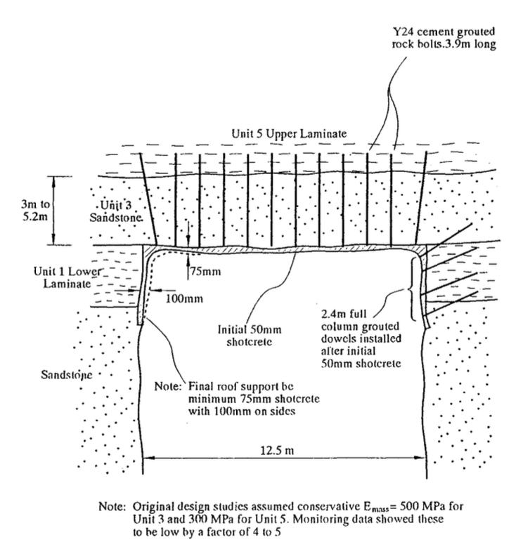


Fig. 1.21: Typical Stress/Structural Failure Along Malabar Outfall

Fig. 1.22: Typical Stress Failures Along the Boomerang Creek Tunnel