Reinforcement and geotextiles in the reinstatement of a highway fill batter, Black Spur, Victoria
1. Project Description
This case history presents an early application of high modulus open grid reinforcement in the restoration of a fill slope in permanent highway works in Victoria. Although a polymer geogrid was proposed in the design, difficulties with supply at that time (1987) led to a combination of galvanised steel mesh and geogrid as soil reinforcement. Geotextiles were also incorporated as drainage layers in the reinforcement and in surface erosion protection.
In August 1985 after a period of heavy rainfall a major landslip occurred on the Maroondah Highway on Black Spur at the 76.2km mark. Here the road is in steep sideling as it climbs through rain forests. The outer edge of formation had been built up over the years from sidecast material. Some 3000 tonnes of earth slipped away from the edge of pavement and across the creek valley below taking all vegetation in its path. An exposed face 30m long and 15m deep was left adjacent to the highway pavement.
2. Technical Considerations and Objectives
A method of restoring the batter and pavement support whilst allowing the road to remain open to traffic along a steep section of winding alignment was needed.
The site is in weathered rhyodacites of the Lake Mountain sequence. The cut is in relatively competent rock but on a very steep hillside. It was impracticable to cut further into this hill to widen the road around the slip. The area is continuously wet in rain forest. The slip had become a mudslide with debris running down to a mountain stream at the toe. The stream feeds the MMBW water supply so the repair work had to include landscaping and removal of the threat of further debris entering the stream.
Geotechnical investigation showed the valley floor comprised soft debris which was unsuitable as a base from which to reconstruct a 1.5:1 batter. Site access and haul distances were unsuitable for importing large fill volumes. An intact base was found by probing not far below the batter midway up the slip, and was chosen as a foundation for a steep reinforced fill batter.
3. Geosynthetic and Reinforcement Selection, Specification and Characteristics
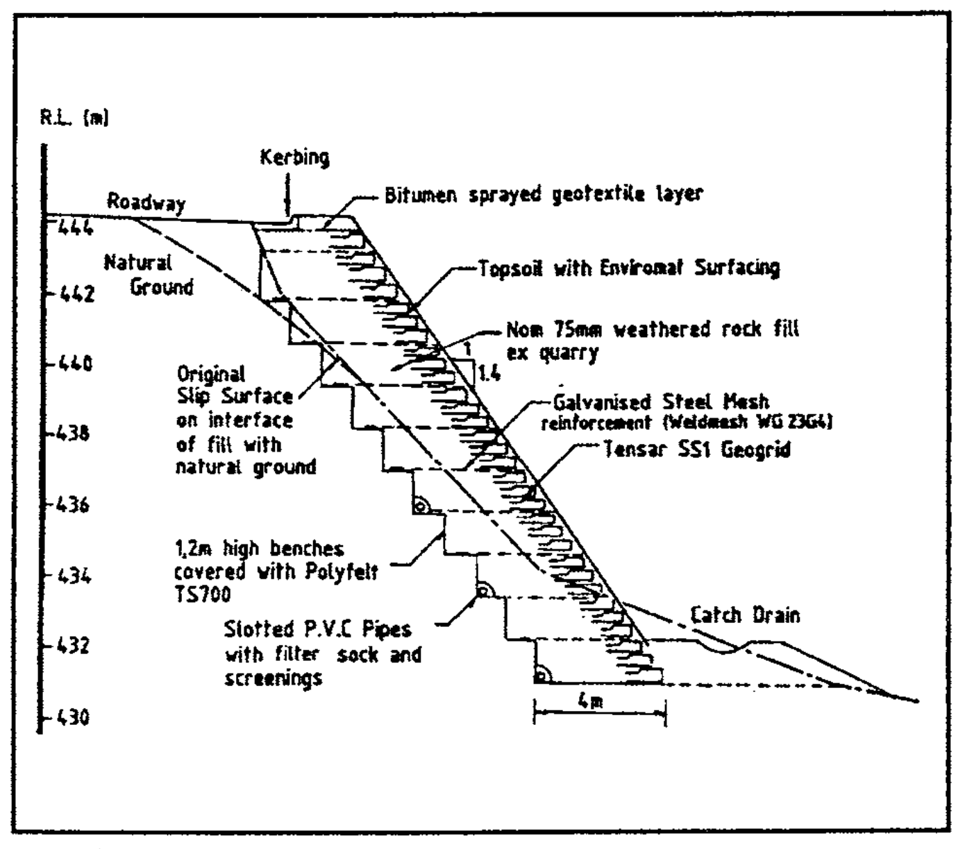
The principle of this type of high fill repair is shown in Figure 1. The combination of high friction compacted granular fills and the inclusion of reinforcement layers with tensile strength and low deformation properties under load allow steep batters to be constructed. For best results, the reinforcement should be an open grid mesh so that the fill can be compacted through the openings to develop full particle interlock and complete integration of the reinforcement. In this case a combination of galvanised WG23G4 steel mesh for main reinforcement and a strain hardened polypropylene mesh (Tensar SS 1) as edge reinforcement and containment was used. The fill was weathered hornfels scalpings from a quarry, 46km distant.
4. Design Technique
The vertical spacing and length requirements for the main Weldmesh reinforcement were evaluated using a two-part wedge analysis for internal stability of the reinforced zone. A friction angle of 40 degrees was used for the weathered hornfels fill, and a factor of safety of 1.5 adopted for reinforcement pull-out. An allowable tensile load of 58 kN/m was adopted for the Weldmesh reinforcement.
For external stability, sliding, overturning and base bearing pressures were checked assuming the reinforced zone acted as a rigid block. The base width of the reinforced fill was chosen to limit the maximum bearing pressure at the fill toe to 120 kPa.
5. Construction
Construction had to be carefully staged and programmed for the driest part of the year (January to March 1987). A trench was excavated down to the intact ground, working along the face of the slip. This undercut the natural ground, old colluvium from natural hillside slips and the remains of the slip material in the upper part of the slip. An advantage of founding the works at this level was that most of the debris lay downslope and the excavations were being made in the more intact stable material that had been left behind in the rear scarp of the slip.
The base trench was excavated using an excavator and dozer in combination and a foundation level of natural material was established. The face of the excavation was lined with Polyfelt non woven geotextile to act as a separation and filter layer.
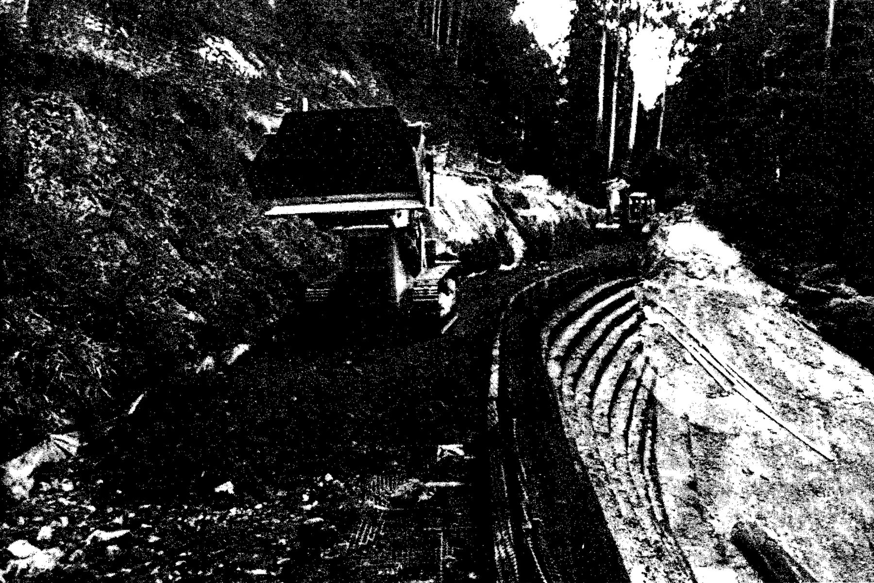
Structural backfill was dumped at the top of the access track and dozed down the track to the base where initial spreading was done by the excavator. In higher layers the excavator fed material from the top to a tracked loader which spread the structural material.
A slip occurred in old fill and colluvium at one end of the trench face early in construction. This was cleaned up and buttressed with a stockpile of the structural backfill. Subsequently, fill was moved out across the work from the “stockpile” in the failed section which was then progressively replaced.
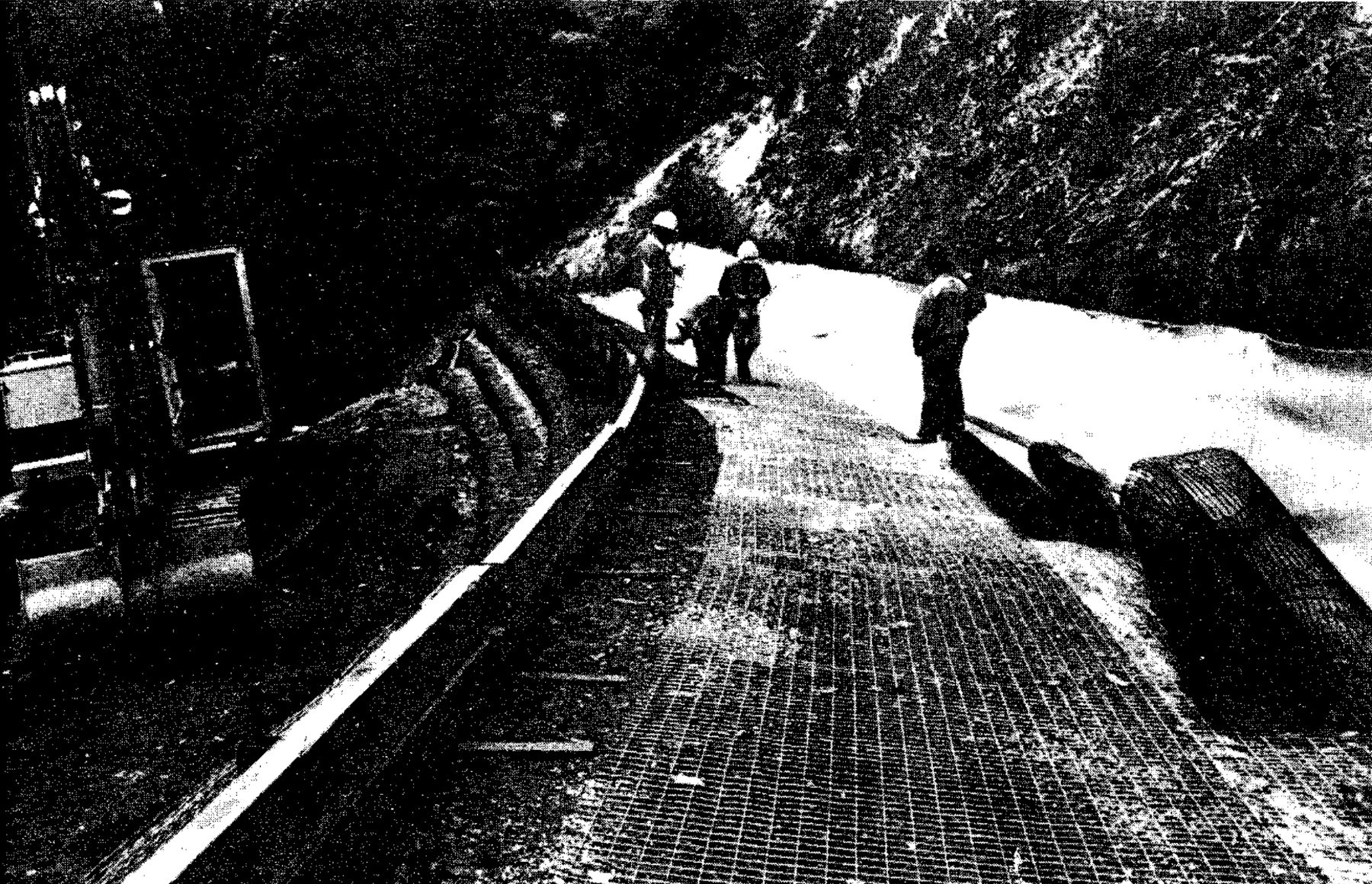
The Weldmesh reinforcement was placed within the fill at 1.2m vertical spacing. Slotted PVC pipe with a filter sock was installed on every second bench with outlets through the filling at the lower end.
The outer edges of batter were wrapped in Tensar geogrid fabric at 400mm intervals. Timber boxing was used for edge support during compaction of the fill, with the timbers being held by special steel braces pegged into the layer below. (See Figure 2).
The geogrid was laid 1m into the fill with a minimum of 300mm overlap between sheets. The structural filling was compacted in 200mm layers (See Figure 3) using a drawn vibrating sheepsfoot roller, with edge compaction being achieved using a vibrating plate. The geogrid was folded back into the embankment by at least 1m and anchored into position with the structural material.
The timber forms were removed and reset for the next layer. The process was repeated in 400mm steps until finished road level was reached.
Drainage outlets were lined with rubble to minimise transportation of sediment into the Maroondah Reservoir catchment. To re-establish a vegetation cover to closely match the original environment many ferns were planted at the base of the new embankment. The batter face was given a thin layer of topsoil and covered with a biodegradable blanket, Enviromat, to protect the geogrid from ultraviolet radiation.
An impervious membrane of geotextile and sprayed bitumen was provided at the underside of verge and a subsurface drain was installed along the pavementl embankment interface.
Kerb and channel was constructed to direct pavement run-off away from the new embankment and the verge was sealed to minimise infiltration into the embankment material. The pavement was restored and guide posts, chevron markers and linemarking completed the re-establishment of the highway.
6. Performance
This treatment provided a well drained reinforced soil buttress along the length of the fill, properly keyed into a stable foundation at the toe. It has performed well since construction in 1987 in an area noted for its high rainfall, whilst natural slopes and filled areas adjoined to the located area have continued to undergo erosion and minor slipping. The batter is now revegetated and blended into the natural surroundings.
7. Conclusion
This type of sideling fill instability is not uncommon on older mountain highways in high rainfall areas. The steep batter reinstatement treatment used here is certainly flexible and relatively inexpensive in the correct circumstances where an adequate stable foundation can be found at the toe and draining through the batter provided for. Stress levels are high and sustained in the reinforcement and materials chosen should be chosen on the basis of only a small proportion of their yield being mobilised, as creep will be a major concern in design on long term stability. In this case geogrids could have been used as main reinforcement, but supply problems led to the choice of the equally satisfactory galvanised steel mesh. Care should always be taken when excavating or benching into steep slip prone country and precautions taken to manage the potential for slip failures.