Piled Foundations for the new SECV Headquarters Building Flinders Street, Melbourne
Introduction
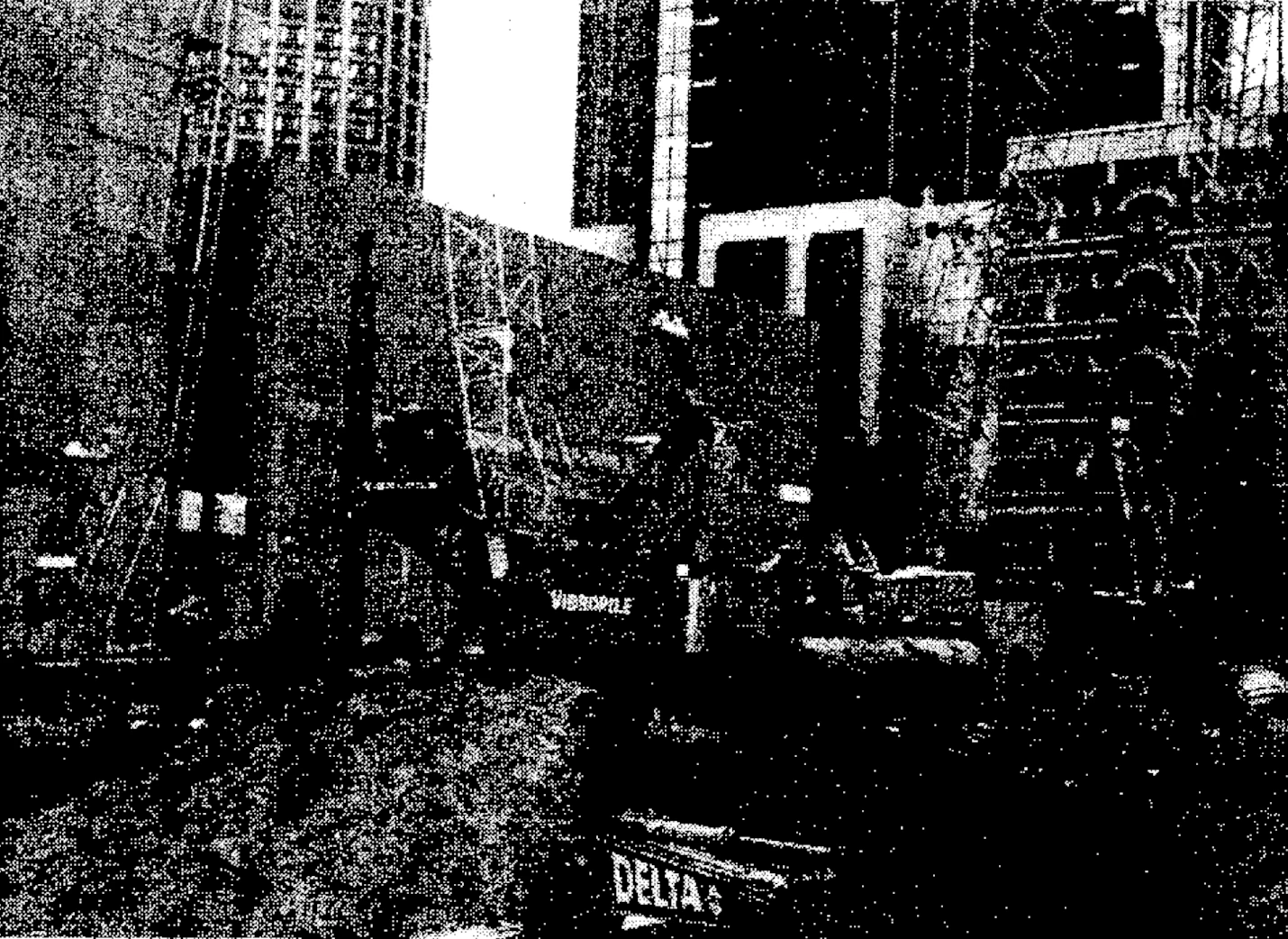
During the first half of 1992, Vibro-Pile (Aust.) Pty Ltd installed the piled foundations for stage three of the SECV Headquarters Building, Flinders Street, Melbourne, which was being constructed by Grocon Ltd. The project included bored piles of 900mm, 1200mmm and 1500mm diameter, with depths to 45 metres, and loads of up to 34MN. Steel soldier-piles and bored cast-in-place secant piling were also installed.
Large contracts involving deep foundations usually have their fair share of problems; this article discusses the resolution of some of the problems (anticipated and otherwise) encountered on this project.
The Project
Work commenced on two fronts with steel soldiers being drilled and placed on the perimeter concurrently with the construction of bored rock-socketed piles, while at the same time demolition proceeded on the old building occupying the site, together with filling of the old basements.
Steel Soldier-Piles
The steel solider-pile installation along the three street boundaries proceeded smoothly, apart from the usual obstacles such as unknown services, concrete and bluestone foundations, and, more difficult to deal with, vertical steel sections from old timber-lagged walls.
These problems were dealt with by a combination of the foreman’s ingenuity, the drill operator’s skill and dogged determination, labourers’ effort, a good measure of compromise from the structural engineers, Meinhardts and co-operation from the M.M.C.
Secant Piling
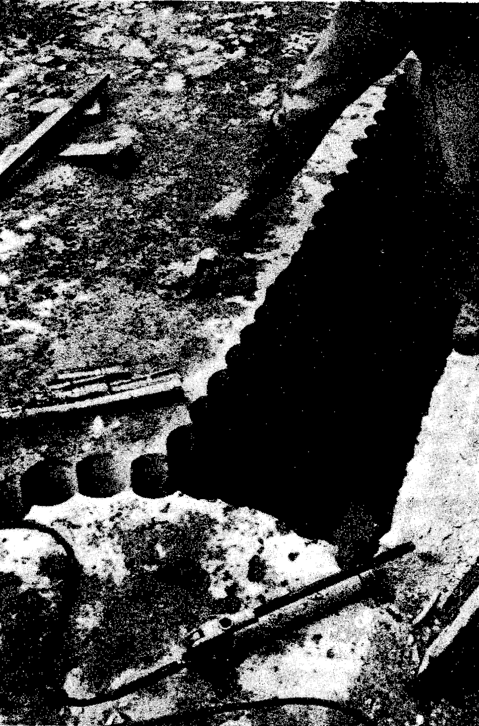
Secant walling was required along the common boundary with an existing building. The upper soil layer was ideal for drilling – a stiff clay – however the existing ground-beam had to be retained until the secant walling was installed. This required the penetration of 1.5 metres of heavily reinforced concrete (including multiple layers of Y-36 bars). This was achieved using diamond-coring and down-the-hole-hammers cutting a profile of the secant wall.
The use of lower-strength concrete in the first run of hit-and-miss unreinforced piles enabled the second run of reinforced infill piles to scallop into the first piles to form an interlocking connection. Upon excavation of the site, the face of the wall was inspected and revealed good sealing characteristics between the intersecting adjacent piles; however, some difficulty in maintaining alignment occurred where over-pour from the adjacent building’s footings tended to deflect the auger, and some minor over-sizing occurred where an old excavation containing unstable fill was encountered. All pretty normal stuff.
Bored Rock-Socketed Piles
The major part of the contract – the rock-socketed piles – provided the major proportion of the challenges.
Geotechnical Background
The ground consisted of some surface filling over stiff clay, then up to 16 metres of sand mudstone, with basalt occurring in some areas. It was the extent of the sand and the proximity of the Yarra River that precluded drilling dry, and indicated the use of bentonite slurry for stabilising the walls of the bored holes.
Because the bentonite slurry would prevent physical inspection and logging of the socket walls and base, the geotechnical consultants, Golder Associates, carried out a prior investigation to enable verification of the materials comprising the socket. Pressure-meter, point-load index and laboratory strength tests were carried out and correlated with the moisture content of rock samples taken from three bore-holes. this enabled rock properties to be estimated from samples taken while the sockets were being drilled. This was done by means of moisture-content testing in a site laboratory.
As the bottom of the socket was being approached, there was some delay,on occasions, while the rock samples were being dried in the site laboratory as part of the moisture-content determinations, and while the calculations were being performed. The calculations followed the method of Williams et al. (Ref. 1). However, the remote determination of socket acceptance did allow the procedure oflowering people into the excavation for inspection and logging to be done away with, thus avoiding the associated delays.
Construction
The sequence of activities following the drilling of the socket for each piles was:
- bentonite recycling and de-sanding
- socket roughening
- bentonite recycling and de-sanding for the second time, and
- base cleaning.
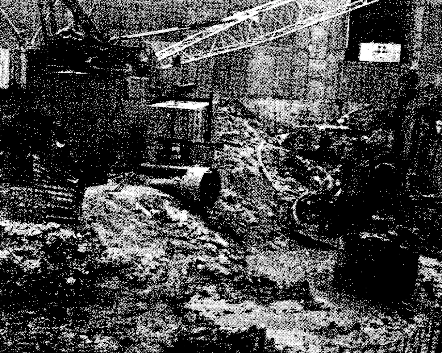
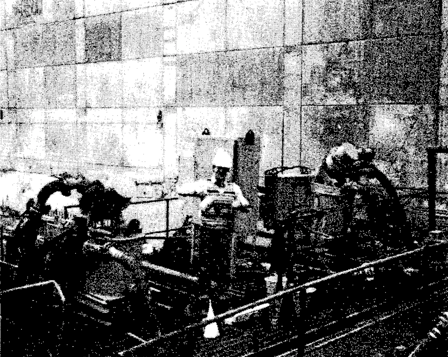
Not until this had been completed to the satisfaction of the geotechnical engineer, could the next phase begin: installing the reinforcing cage, assembling and placing the tremie, and finally, placing the concrete, either by pump or direct from the chute to the tremie on the occasions that access allowed this. The sequential nature of the above activities, and their duration required 12-hour shifts to be worked. The congestion on the site precluded the use of a second drill rig to speed up the work for all but a limited number of piles.
Bentonite
Basements occupied a large area of the site, and substantial filling was placed to bring the working surface above the level of the nearby Yarra River, so as to enable a positive pressure head of bentonite to be maintained during drilling.
Constant vigilance was required to ensure the bentonite level was maintained above the water table at all times, once the sand layer was penetrated by the auger.
The bentonite was not introduced into the holes while drilling the top clay layers so that the dry clay spoil could be used as fill elsewhere on the site. However, as the sand layer was approached, the risk of a blow-in necessitated that the bentonite be added while the auger was still drilling the clay. At this stage, a dramatic drop in the rate of advancement occurred, due to the drill tools plugging in the clay-bentonite mix. This problem was rectified, after some trial and error, by modifications to the drilling tools.
Special drilling tools as well as extra drill-operator care were needed while penetrating the sand layer, which was up to 16 metres thick in some piles. the particular problem here was the high suction effect when withdrawing an auger bucket, making scour and collapse of the sand a constant threat.
The risk of loss of bentonite into neighbouring basements from piles drilled close to boundaries where the soil might have been disturbed by previous excavations, should not be overlooked by contractors contemplating this type of work. Despite installing extra-long steel casing on these piles, there were occasions when the neighbouring basement car-park operator became most irate, as his customers had to step through ever-widening pools of bentonite slurry to get to their cars. The ground, disturbed by the neighbouring building’s previous construction, was the problem, and bentonite loss was controlled by drilling over-size, letting the loose backfill collapse, placing weak concrete, then re-drilling on-size through the concrete.
Concreting
After the reinforcing-cage and tremie were put into position and checked for levels, the concreting phase was able to be started. A high-slump mix was selected using a long-retardation super-plasticiser. This gave some leeway should a plant break-down have occurred. A second advantage was the concrete in the entire socket was still plastic when the concrete pour was completed, allowing the full concreted head to establish the maximum lateral stress against the socket walls.
Owing to the low cut-off levels, and the risk of loose material falling in and contaminating the concrete, the steel liner and the remaining bentonite were left in place until the next day.
Concluding Comments
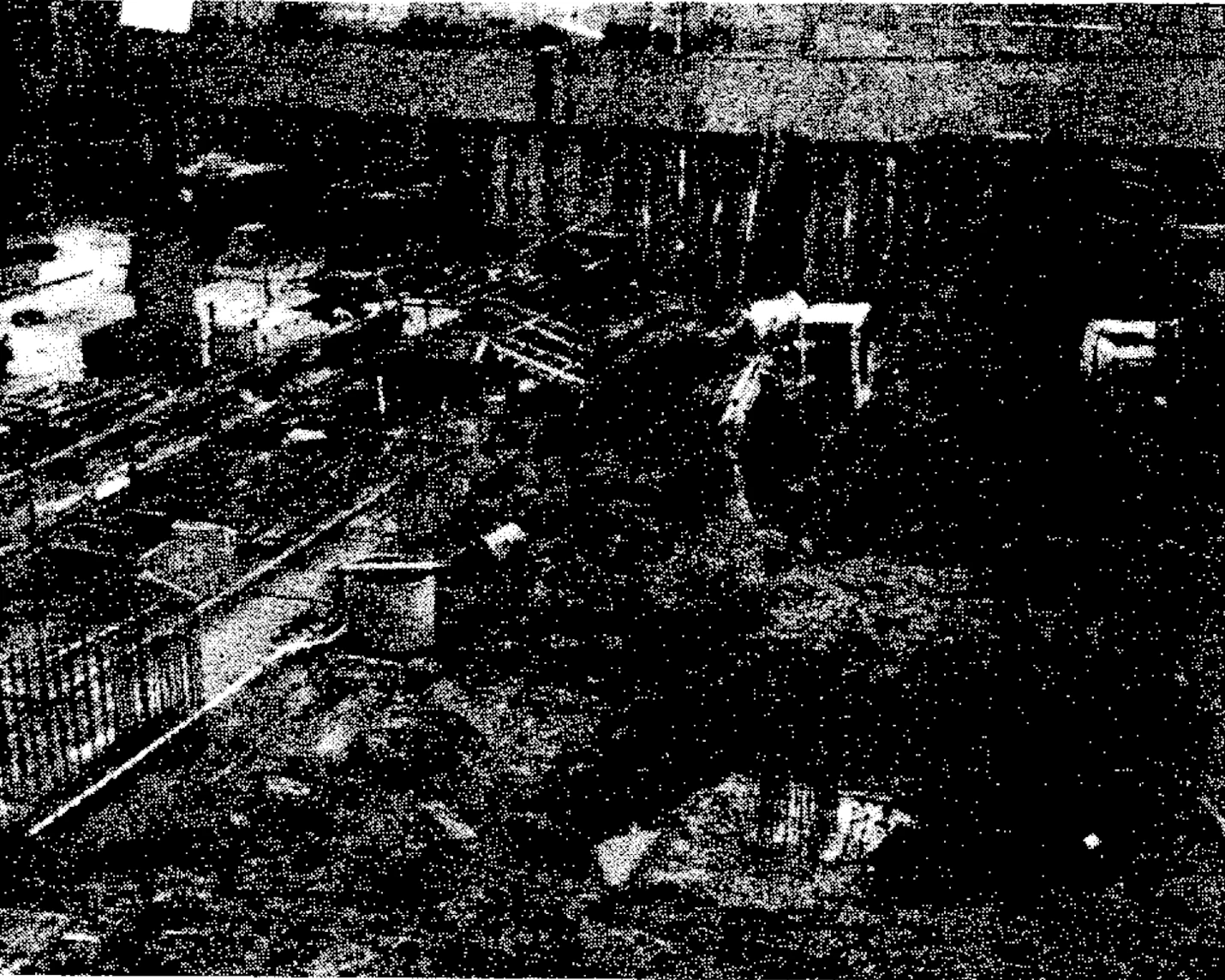
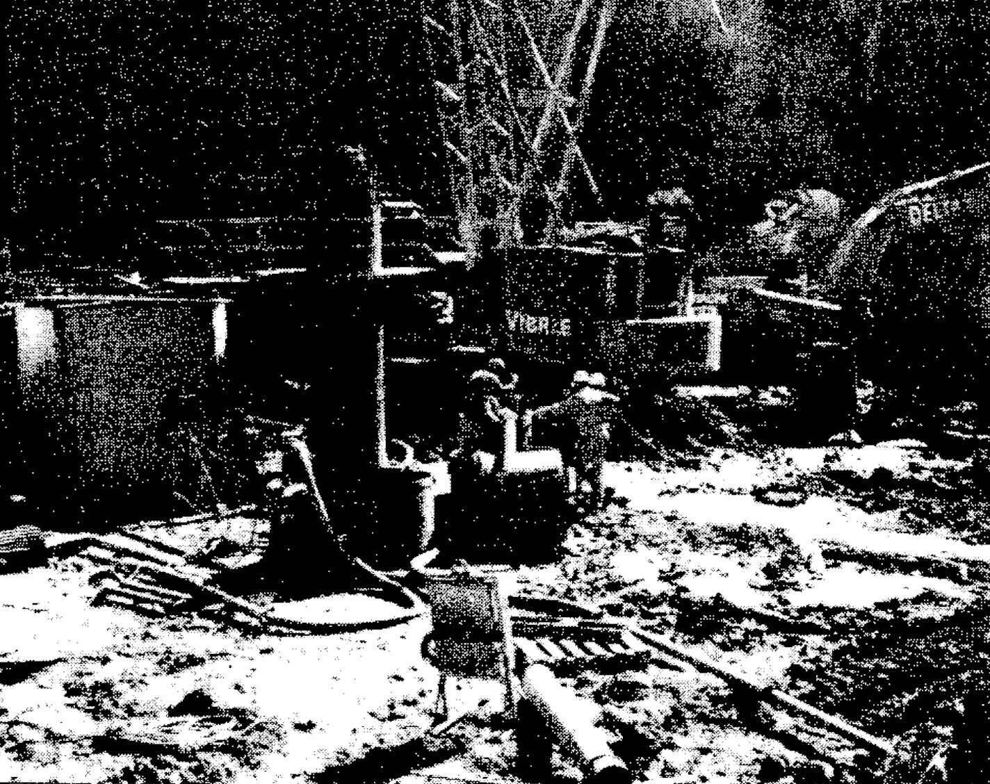
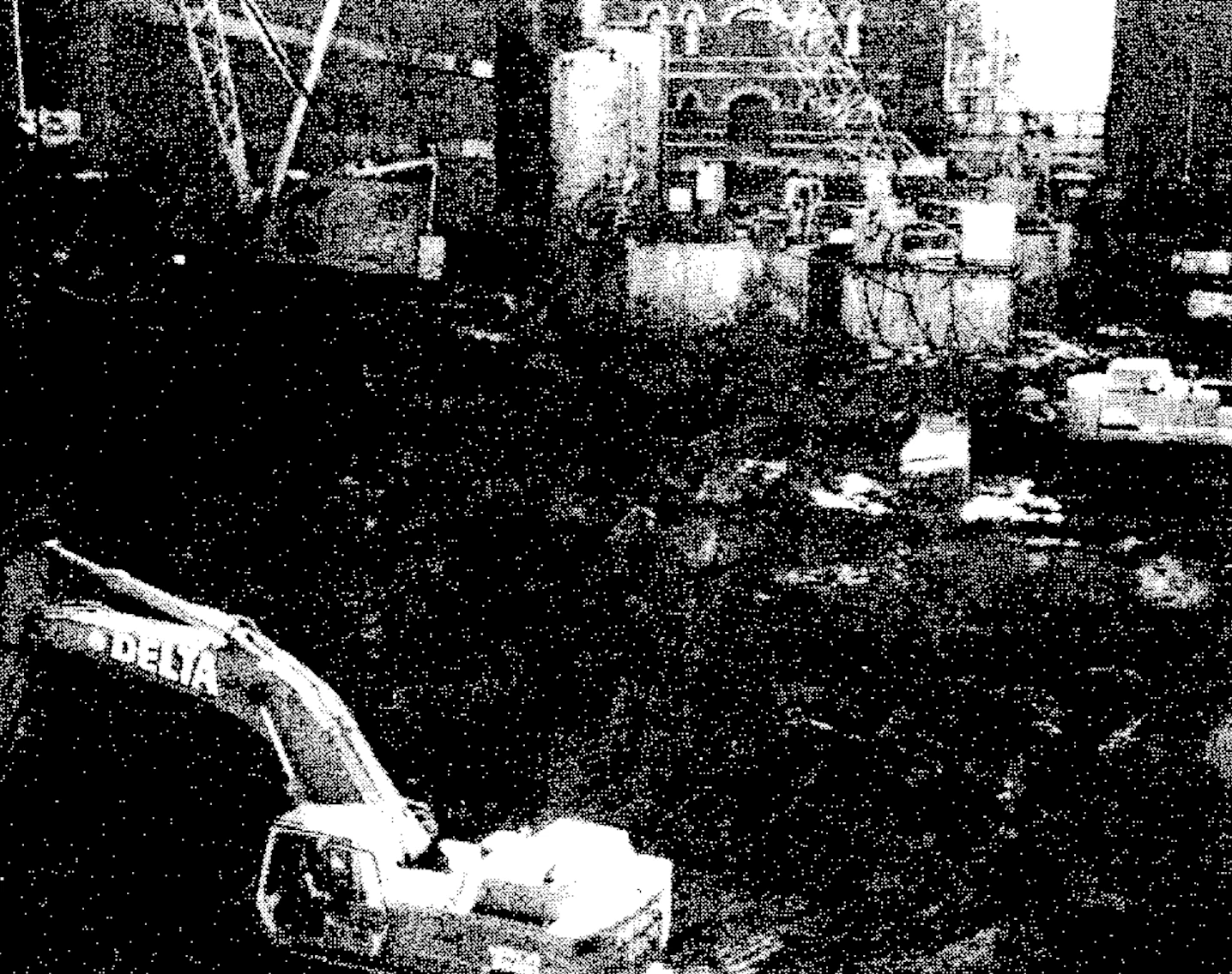
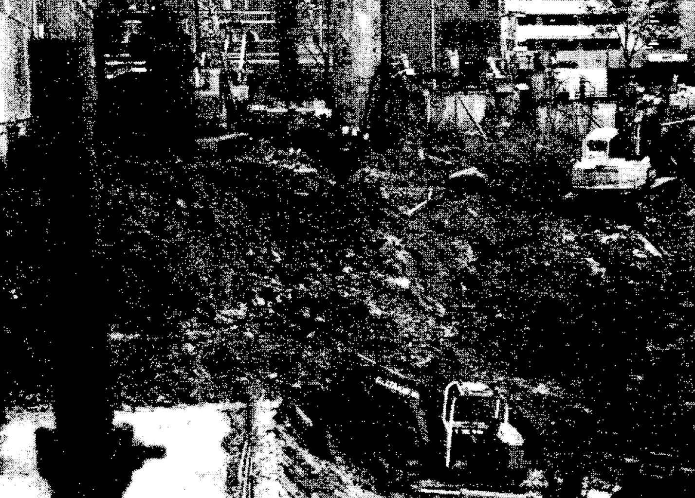
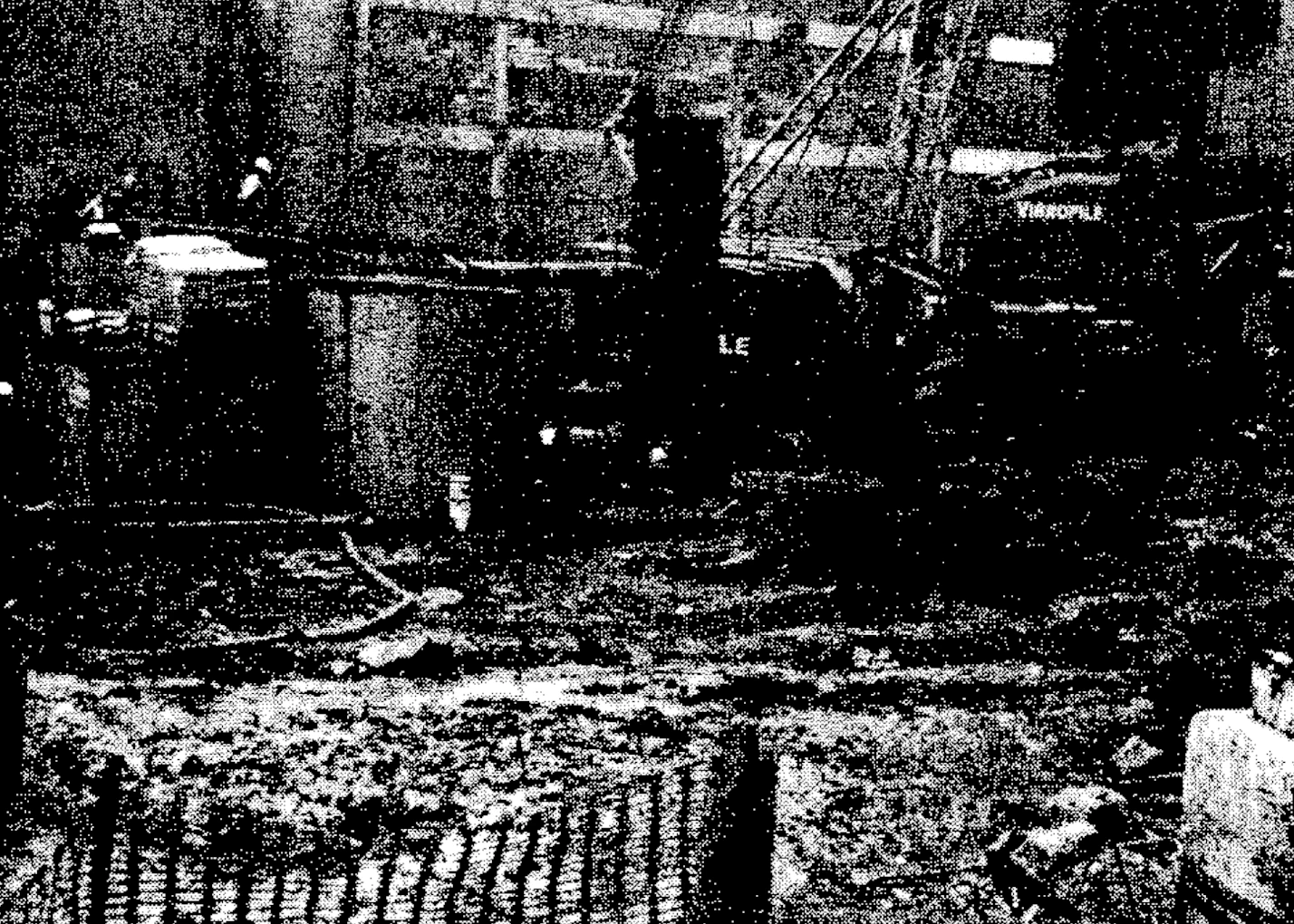
The moisture content method employed by Golders to assess the rock strength without personnel having to enter the excavation may become more common in the future, even for holes not drilled under a drilling fluid, in the interests of safety and time savings. Through no fault of our own, we were working in what looked like a bomb site rather than a building site, and we pined for the good old days when piling contractors enjoyed exclusive possession of a site for almost the entire duration of their contract. Concurrent massive demolition of reinforced concrete with sophisticated deep foundation contracts is hardly conducive to efficient operations.
To add insult to injury, just as we completed a group of piles and were relishing the thought of utilising the clear space, the bulk excavation contractor moved in and turned our space into a gaping hole. We were left teetering on the edge of a cliff face, the stability of which defied all the laws of soil mechanics, while we contemplated the ever-diminishing proportions of our hopelessly inadequate site space. Oh well, who was it who said “Life wasn’t meant…” ?
On completion of the project and having demonstrated to the site geotechnical engineer in fine detail our methods for the construction of bored rock-socketed piles under bentonite, we were somewhat miffed at his speedy departure (complete with up-to-date training) from the employ of the consultant to that of our opposition. Perhaps we should have been flattered at the value placed on geotechnical engineering experience gained on a Vibro-Pile project!
Reference1
Williams, A.F., Johnston, I.W. and Donald, I.E. “The design of socketed piles in weak rock” Proceedings, International Conference on Structural Foundations on Rock, Sydney (1980).