Design and construction of a synthetic membrane cover to a large active sewage treatment lagoon
Summary
Melbourne Water has recently embarked on an odour control program at the Werribee Treatment Complex which involves modifying the lagoon operation by the addition of electrical-mechanical surface aerators and the fitting of floating flexible membrane covers to the existing anaerobic zones. This paper describes aspects of the design and construction of the first of these covers to be fitted over the contained anaerobic zone in the 115 East lagoon.
1. Introduction
The Werribee Sewage Treatment Complex on the outskirts of Melbourne is one of the most extensive farm and lagoon waste water treatment facilities in the world. Formerly in a rural location it is now being encroached upon by development. As a part of a program intended to reduce odour emissions, improve anaerobic efficiency and allow capture of methane gas for energy a floating flexible membrane liner cover has been installed over the anaerobic zone of one of the major treatment lagoons at the Werrlbee Treatment Complex.
This pioneering project is the first municipal waste water cover in Australia and with an area of some 3.5 hectares is the largest of its type in the world. Similar floating covers have been used for waste water treatment to industrial facilities but this is the first cover for municipal sewage treatment.
This cover is the first of a series planned at the Werribee Treatment Complex. The captured odour and methane gases will eventually be combusted to produce enough electricity to make the lagoon systems self sufficient in energy requirements.
2. Werribee Treatment Complex
The Werribee Treatment Complex (or Farm as it is more commonly known) has been in operation for over 100 years treating industrial and domestic waste water from the City of Melbourne. It is situated on some 11,000 hectares of relatively flat land adjacent to Port Phillip Bay some 33 km to the South West of the City. Currently it treats about 520 ML/day of wastewater of which about 25% is industrial in origin.
The treatment methods in use are as follows:
- Land Filtration. With this method raw or settled waste water is flood irrigated onto pasture which after an interval is grazed by livestock. This system is only effective in the summer growing period of November to April when evaporation rates are also higher.
- Grass Filtration. This method is utilised in the cooler months and involves steady flows of settled sewage across fields of tall grass. The process is effectively horizontal trickle filtration with the grass stems developing an effective biofilm cover on the stems.
- Lagoons. A typical lagoon system is comprised of a number of ponds in series. These ponds vary in functional mode from anaerobic to facultative to aerobic. The shift in mode is influenced by ambient temperature and is further managed by control of sewage inflows and the balance of raw and settled sewage.
- Primary Sedimentation. This is conducted on some of the sewage in relatively deep earthen tanks which are desludgedweekly.
- Sludge Digestion. Sludge digestion is carried out in two open lagoons of dimensions 180m by 550 m. They are desludged every two to three years.
In recent times the increased flow to the Werrlbee Treatment Complex and an awareness of the diminishing remoteness of the treatment site has focussed attention on its odour management.
This has lead to an ongoing series of studies and observation programs to ascertain the extent of gas and odour influence in the region and to identify the primary sources. These surveys lead to a conclusion that one of the primary sources of gas and odour was the initial anaerobic component of the lagoon series.
In September 1989 surface aerators were retrofitted to ponds 1 and 2 of the 115 East lagoon. A floating barrier was used to separate the anaerobic zone from the remainder of the pond where the aerators were installed. The aerators were successful in removing the odour in the zone in which they were fitted. Subsequent installations of surface aerators on the 55 East lagoon have been equally as successful in reducing odours.
Plans were prepared in 1990 to cover the anaerobic zone of the lagoon so that an ‘odourless’ lagoon system could be demonstrated. The anaerobic zone cover on the 115 East lagoon was the first of these planned covers. The captured methane gas produced by the anaerobic process was seen as a potential source of renewable energy for the generation of electricity and raising the temperature of the sewage effluent in the lagoon.
3. Lagoon Cover Program
Floating lagoon and reservoir covers constructed from flexible synthetic membrane liner materials have been used extensively over the last 15-20 years but their use has been confined to clean water storage and relatively small lagoons for industrial waste water treatment in the food processing industry where the BOD loadings are comparatively high.
Melbourne water had a desire to take this basic cover technology and develop it further for its needs related to large scale waste water treatment. Some of the particular areas of concern and interest were:
- Structural stability over a large lagoon subjected frequently to strong winds
- Failsafe operational security of the cover system and gas handling system
- Adequate service life expectation from the cover material in the face of the effiuent and gas exposure and the UV radiation exposure as well as other environmental influences.
- The storage of methane gas under the cover so that advantage could be taken of electricity generation during peak hour tariff periods and the gas accumulated whist grid electricity is used during off-peak times. This lead to a strong interest in systems and materials that offered gas storage potential.
Examination of available systems indicated that some of these desirable features were in direct conflict with each other. For instance the high strength reinforced synthetic cover materials that leant themselves to tensioned cover structures with gas storage potential did not have as good a track record in terms of UV and environmental exposure as simpler unreinforced polymer materials that required a simpler design philosophy based on restraint by an operational suction under the cover.
In late 1991 Melbourne Water called tenders on a design and construct basis for a cover to the confined anaerobic zone of the 115E lagoon. This is the smallest of the lagoons in the cover program and the tender documents called for covers utilising High Density Polyethylene (HDPE). HDPE is a highly crystalline form of polyethylene and is known to have excellent UV and general chemical exposure characteristics. It requires a suction restraint based design philosophy for such covers and this was recognised by the documents which also called for proposals that may enable gas storage now or in the future. The documents also called for a gas handling and flaring facility capable of drawing the gas off at a controlled suction and disposing of it by flaring and providing various instruments etc for evaluation of the gas production.
Plans were also made for the implementation of a small proving capacity power generation facility to operate on gas drawn from the gas handling facility.
The contract for this work was let to Polyfelt Geosynthetics Pty Ltd with the HDPE liner material and cover design being provided by Gundle Lining Inc of Houston and the gas handling and flaring facility sub-contracted to Fluid Waste Treatment Pty Ltd.
4. The 115E Lagoon
The first pond of the 115E lagoon is some 150 m wide and 1100 m long, 3 m deep and is oriented with the sewage inflow at the NNE end. It takes an inflow of around 50 MUday of raw unscreened sewage.
The cover is installed over the initial 230 m which is the confined anaerobic zone. This area had already been separated from the aerobic part of the pond downstream by floating boom type barrier. The earlier retrofitting of surface aerators downstream of the floating barrier had created aerobic (non-odourous) conditions in the remainder of pond 1 and pond 2.
Prior to installation of the cover measurements had indicated that the uncovered anaerobic zone was reducing the BOD of the effiuent from around 500 mg/l to 150 mg/l. The level of turbulence due to gas generation was found to be preventing sludge build up and the cover could be installed without need to consider future desludging of the covered anaerobic zone.
The lagoon embankments were built using compacted clay and were protected from wave action by rock armour beaching which required removal before construction of the cover. These embankments also provide access roadways for Werribee Treatment Complex personnel and the roadway width reduction as a result of the cover installation was to be minimised.
The embankments were to provide fixing capacity on three sides of the pond and an alternative ‘fourth wall’ fixing method was required at the Southern end of the cover. This wall was permitted to be of structural or other construction provided it did nor allow gas escape and did not impede the flow of sewage down the pond.
5. Cover Design
The basic parameters specified for the cover design included the following:
- Surface wind velocity 130 km/hr
- Ambient air temperature -5°C to 45°C
- Cover to operate generally under a slight vacuum or suction pressure
- Maximum gas production 20,000 cu.m/day
- Maximum fluctuation in floating cover level 100 mm.
- Service life guarantee on cover material of 15 years
The cover design is based on the use of 2.5 mm thick HDPE extruded liner material which uses the same basic polymer as black polyethylene pipe and is known to provide excellent long term exposed weathering performance and excellent chemical exposure resistance. The material density of HDPE is 0.94 and it therefore floats on water unaided.
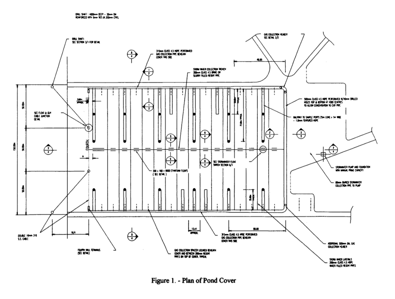
In order to provide control over the cover shape and thereby control the flow of gas under the cover and the flow of surface storm water a skeletal system of ballast filled HDPE pipes with supplementary floats was fitted over the cover. This can be seen in Figure 1.
The main longitudinal pipe is 315 mm dia and filled with cement slurry and the lateral pipes are 200 mm dia and filled with water. The lateral pipes are at a nominal 13.5 m spacing to correspond with every second seam in the 6.86m wide HDPE cover material and are anchored to concrete blocks set into the embankment crest. These pipes not only control the shape of the cover and allow storm water management but also provide additional ballasting potential against wind loadings particularly if the cover is allowed to inflate and store gas.
The weight pipe system directs gas flows to the lagoon batters to facilitate its collection by a peripheral pipe system under the cover at the batter crest which varies from 315 mm to 500 mm diameter. The three sides of the cover with batters are anchored and sealed by placing of the cover material into an anchor trench which is carefully backfilled with compacted clay.
The ‘fourth wall’ is achieved by a stayed cable system with floats and a 1.5 m deep skirt restrained by a slurry filled end pipe. Concrete anchor points at the two ‘fourth wall’ corners required the embedment of special HDPE sealing strips into the concrete with clay and stabilised sand backfill.
The cover is intended for operation with a small internal vacuum maintained by external gas pumps and although some gas inflation for storage is possible a fully deflated condition must be maintained during periods of high winds.
Supplementary aspects of the design included the following:
- A storm water pump facility situated on the embankment crest with a long suction line and float switches to direct water collected in the trench, formed by the longitudinal weight pipe, to the incoming sewage channel.
- Combined sampling/venting ports with a sliding pipe connection capable of controlling the maximum inflation of the cover in their immediate vicinity.
- Textured HDPE sheet walkways to provide strategic access particularly to the sampling ports
- A gas collection pipe system sized to meet the needs of rapid drawdown in the face of an impending wind event if the cover is used for gas storage.
6. Cover Construction
In order to construct the cover over the operating anaerobic lagoon construction has been carried out using a temporary barge floating on top of the sludge. The barge has been used to support the cover as it is welded together in panels prior to moving the barge forward to the next position. This method enabled effective progressive anchoring of the cover against wind uplift as the work proceeded. During construction temporary gas extraction fans were used to draw gas from under the cover and exhaust it to air via a venting stack in a suitably remote location.
The cover construction was controlled using a contractor effected quality management system which exceeded the requirements of AS 2990 Category B.
Most of the cover was welded together using hot wedge welding devices which produce a double weld with an internal air gap for integrity testing. Other welding was carried out with extrusion welding techniques. All of the welding was subjected to non-destructive evaluation techniques involving either internal pressure or vacuum testing and strategic destructive test samples were taken under the direction of a third party quality auditor.
Special techniques developed by the contractor to avoid wind damage during construction were generally effective with one incident occurring which required repairs and reinstatement of wind damage to a partially fixed section of the cover.
7. Gas Handling
A HDPE collection pipe system collects the gas from under the cover at the batter crests and this is connected to a stainless steel gas train and gas handling system at the Northern corner of the cover.
The gas handling system includes the following components:
- A duplicate gas pumplblower system to provide the suction to extract the gas and direct it through the system.
- A bypass to enable low gas flows to be handled without excessive suction fluctuation.
- Sedimentation and condensate traps to enable long term operation of the system.
- An LPG fired gas flare designed for use in exposed locations.
- Sensors and instrumentation to enable constant evaluation of parameters such as suction pressure, flow rate and gas characteristics.
- An electronic control system to enable automatic control of the systems functions and transmission of data into the Werribee Treatment Complex telemetry system.
The gas train was pre-assembled and tested on a factory based skid before transport to site for final assembly and test.
Pioneers and Murphy
Murphy was the fellow who suggested that, particularly in critical circumstances, whatever can go wrong will go wrong. Irrespective of planning and forethought a pioneering project such as this can not be expected to escape unscathed from a few difficulties.
Some of the difficulties faced on this project include:
A build-up of semi-solid scum material under the cover in the NE corner of the lagoon which influences the gas production and behaviour under the cover and the surface water behaviour on top of the cover. Action has been taken to regulate the sewage inflow and this scum is expected to dissipate over a warm season of operation.
Sensitivity of the functional behaviour and performance of the cover to small variations in under cover pressure differentials caused by atmospheric conditions.
Inconsistent release of gas from under the cover particularly in periods of relatively low gas production and the influence of higher suction pressures as may occur in rapid draw-down from an inflated state. This can be attributed to a ballooning tendency in the cover which is seen to be a result of excessive ‘fullness’ developed during construction.
In spite of these difficulties the cover in November 1992 is seen to be producing gas at a rate of around 8000 cu.mlday and although there is some undesirable distortion of the cover shape the gas handling train is able to handle this relatively unsteady gas flow without great difficulty.
A small 300 kVa generator facility has been connected to take gas from the cover and produce electricity for the operation of the first group of aerators in pond 1.
8. Conclusions
Melbourne Water has successfully embarked on a pioneering exercise involving the first of several planned floating flexible membrane covers to the anaerobic lagoons at the Werribee Sewage Treatment Complex. The cover is collecting gas which has been used for trial power generation and has survived some strong wind events without mishap. The covers should form an effective part of the odour control program and offer the potential for sludge gas energy utilisation.
Covers such as this provide potential solutions to odour problems at both municipal and industrial waste water treatment facilities. As well as odour control they offer potential for improved anaerobic activity and gas utilisation in an energy conscious world.
10. References
Gulovsen, T., Hansen, P., Hutchison, D., Russell, J. and Scott, P. Odour Minimisation at Werribee, AWWA Water Journal June 1992.
Melbourne Water (1992). Contract No. 4524. Design, Supply Installation, Commissioning and Maintenance of a Floating Cover Gas Collection and Flaring Facilities on 115 East Lagoon at Werribee Treatment Complex.
Sadlier, M. (1989). The Role of Synthetic Liners in Waste Management, Proceedings Fifth National Local Government Engineering Conference, Sydney.