Comparison of methods for determining retaining wall earth pressures from surface line loads
Synopsis
The lateral pressures acting on the wall stem from externally applied line loads for concrete cantilever retaining walls are considered. These lateral pressures are of concern as the design of the structural components of these retaining walls is greatly influenced by the lateral earth pressures acting on the wall stem. Two common analytical methods and the finite element method, were used to evaluate these earth pressures. The lateral pressures predicted by the finite element method differed from the predictions from conventional techniques based on elastic theory. These differences can be attributed to .the erroneous implication in elastic theory that any combination of effective principal stress ratio is possible for the backfill soil.
1. Introduction
To date, very limited numerical studies have been carried out to investigate the behaviour of concrete cantilever walls. The results presented in this paper are part of an ongoing project to examine the behaviour of concrete cantilever retaining walls. This paper focuses on the prediction of the lateral stresses acting on the wall stem under working load conditions, from vertical surcharge line loads acting on the surface of the backfill. These lateral pressures are of concern as the design of the structural components of these retaining walls is greatly influenced by the lateral earth pressures acting on the wall stem. Two common analytical methods as well as the finite element method, were used to evaluate these earth pressures.
2. Review of conventional methods
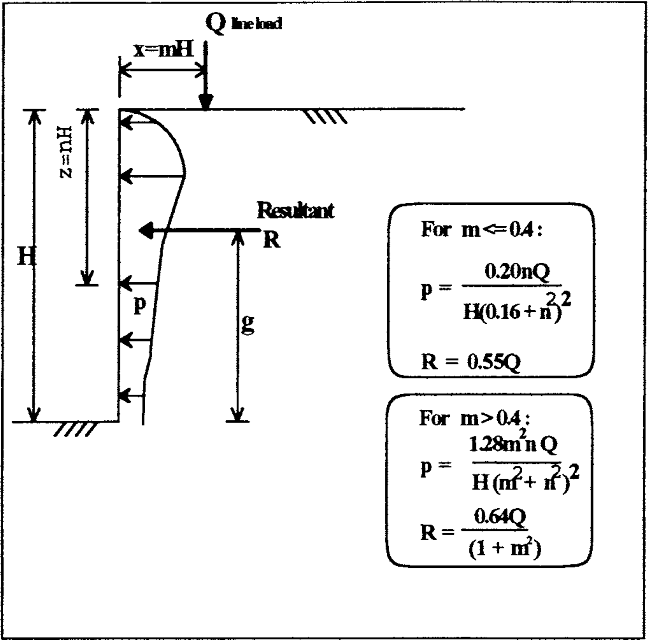
For a surcharge line load placed at the surface of the backfill of a gravity type retaining wall, most textbooks and design Codes rely on the theory of elasticity to compute the lateral pressures acting on the wall back. Fig. l(a) illustrates a typical design method found in many textbooks. The equations for the lateral pressure (P) were derived from elastic theory with the assumption that the wall is unyielding and rigid, and then slightly modified to agree with experimental findings (Terzaghi, 1954). As pointed out by Clayton and Milititsky (1986), the main criticism of this approach for determining the horizontal pressure acting on the wall relates to the implicit assumption that the strength of the soil is infinite. This implies that any combination of effective principal stress ratio is possible for the backfill soil. In reality, the effective principal stress ratios are limited to less than, or equal to, the value at which failure occurs. This constraint has particular relevance for gravity and semi-gravity retaining walls since the backfill in the vicinity of the wall back is usually in the active (failure) condition as highlighted by the finite element analyses presented later.
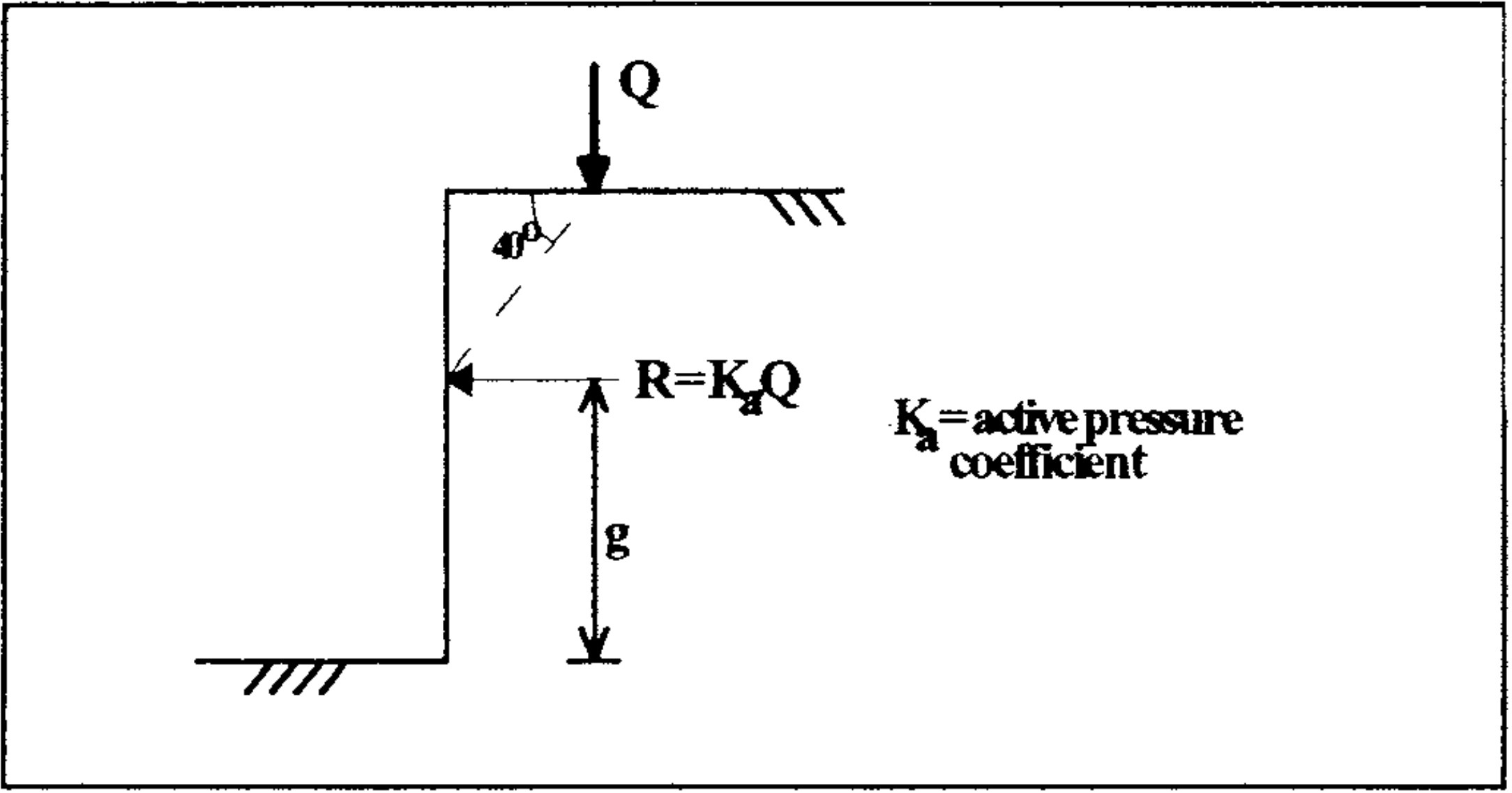
Another common approach is the empirical technique suggested by CP2 (1951) based on Terzaghi and Peck (1948) and shown in Fig. 1(b). The line load is considered to exert a horizontal force of magnitude on the wall with its point of application as indicated. This method which is essentially based on the Coulomb (1776) wedge graphical approach gives results entirely different from experimental findings (Terzaghi, 1954).
3. Finite element methodology
A plane-strain finite element program was used in the analyses. The program essentially followed the ‘initial stress’ finite element formulations of Nayak and Zienkiewicz (1972). Eight-noded isoparametric elements with reduced integration were used to model the soil and wall elements. The soil was modelled as linear elastic-perfectly plastic with a Mohr-Coulomb yield surface, and associated flow conditions have been assumed. The wall was assumed to behave linear elastically. Six-noded interface elements based on the Goodman et al. (1968) model were employed to model the interaction between the soil and the structure. The interface shear stress-displacement constitutive model adopted was essentially similar to the model used by Clough and Duncan (1971). Only the analyses assuming a perfectly smooth wall back are presented here as the analyses with a rough wall back indicated the same trends, and have been omitted for brevity. The stage-by-stage placement of the wall and backfill were simulated using the technique proposed by Clough (1971). The cohesionless backfill was assumed to be loosely placed or very lightly compacted with . Compaction effects such as the finite element simulation procedures proposed by Seed and Duncan (1986) were not considered. The analysis was carried out in 12 increments for the placement of the wall and backfill and 3 increments for the applied line load. Further details of the finite element modelling are described in Goh (1993).
4. Wall configuration
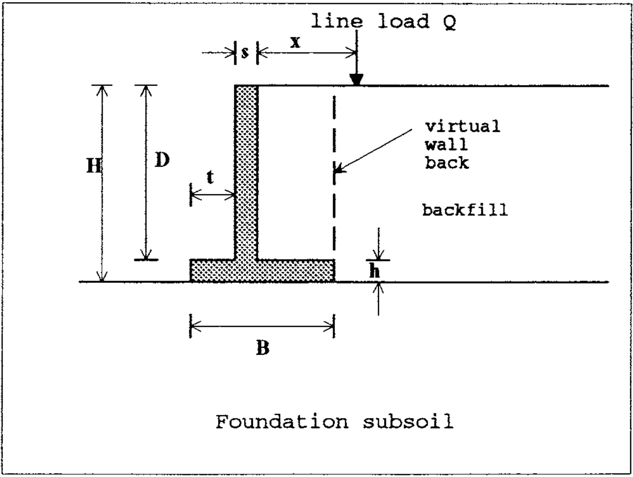
Table 1 summarises the details of the wall dimensions and properties, and the soil properties. The strength and initial stiffness properties of the foundation subsoil and backfill soil are essentially similar to those used by Clough and Duncan (1971). Both a 3 m high and a 6 m high concrete cantilever retaining wall were considered. Different magnitudes of as well as distance () of away from the wall back were considered, and the details are summarised in Table 2.
In the problems analysed, the factors of safety based on CP2 (1951) were between 1.45 and 1.75 for sliding failure, and between 2.0 and 3.0 for overturning failure. Note that in any computations of the retaining wall safety factors against sliding and overturning, it is the horizontal stresses acting on the vertical plane passing through the heel of the wall (virtual back) that are of major concern. However as emphasised earlier, the main focus in this paper is on the stresses acting on the wall stem under practical working load conditions. The lateral stresses acting on the wall stem are generally of interest for the structural design of the reinforced concrete wall. One common practice in design is to modify the lateral pressures acting on the wall stem by multiplying the pressure by a load factor which usually has a value greater than unity.
5. Finite element results
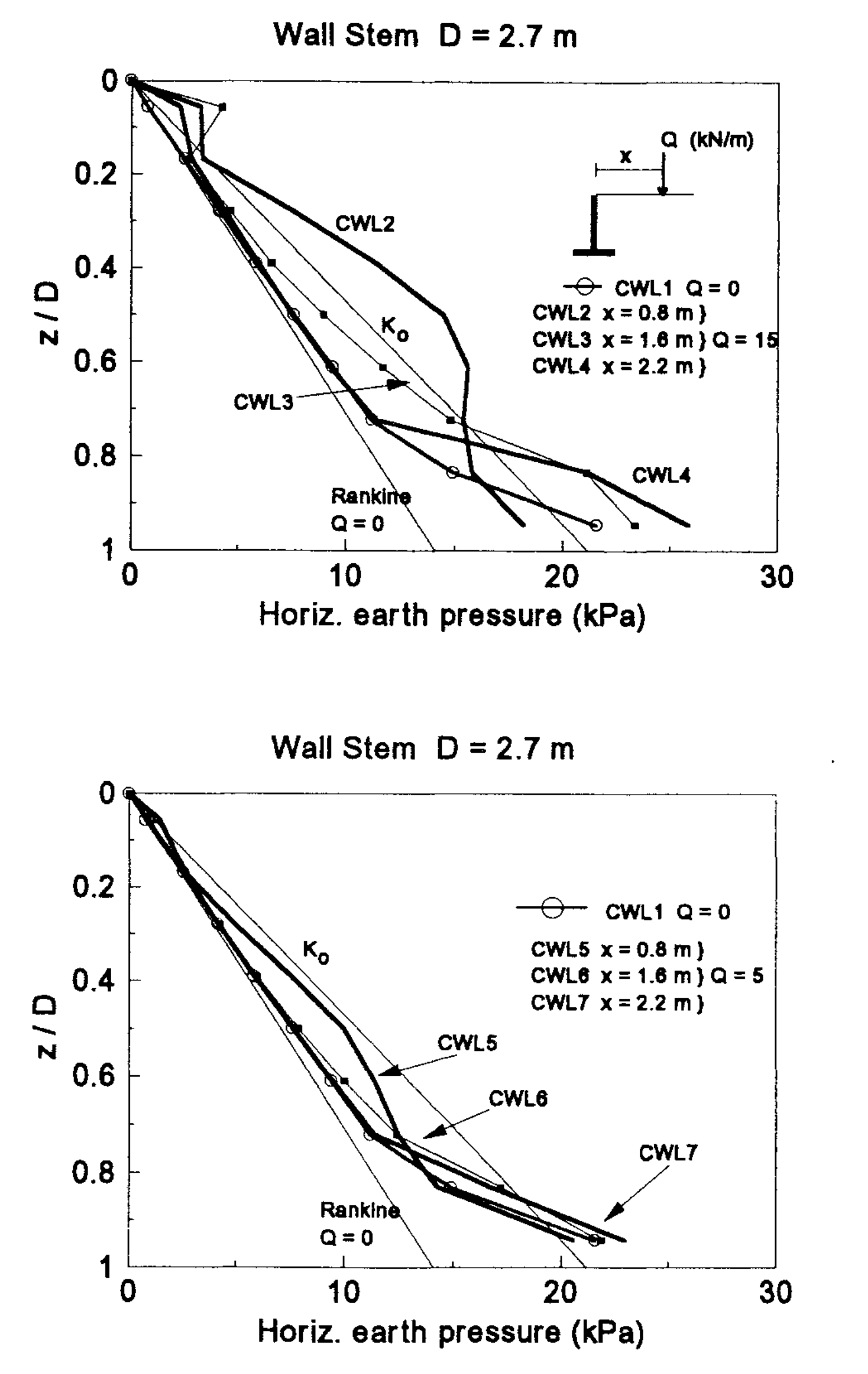
Fig. 3 shows some typical finite element predictions of the lateral pressures acting on the wall back. z is the depth of the soil below the top of the backfill. The theoretical at-rest and Rankine (1857) active earth pressures () as well as the finite element lateral pressures at the end of backfilling (CWL1) are also shown. At the end of backfilling, the predicted lateral pressures correspond closely to the classical Rankine active pressures for the top two-thirds of the wall. In the lower third of the stem, the predicted lateral pressures are significantly in excess of the active pressures, because of infsufficient lateral yielding of the wall stem (Goh, 1993).
The applied load resulted in significantly larger lateral pressures on the wall stem when the line load is close to the wall back (CWL2, CWL3 and CWL5). The results suggest that the lateral pressures are influenced by the magnitude and line of action of the line load. For CWL2 and CWL5, the lateral pressures close to the bottom of the wall stem are smaller than at the end of backfilling (CWL1). This is likely to be due to the horizontal stress release from the lateral movement of the wall away from the backfill after the line load is applied.
| Property | Symbol | Value |
|---|---|---|
| Wall Properties | ||
| Wall base width (m) | 1.7 | |
| Wall toe width (m) | 0.4 | |
| Wall stem thickness (m) | 0.3 | |
| Wall heel thickness (m) | 0.3, 0.6 | |
| Wall height (m) | 3.0, 6.0 | |
| Wall stem height (m) | 2.7, 5.4 | |
| Young’s modulus ( MPa) | 25 | |
| Poisson’s ratio | 0.2 | |
| Unit weight (kN/m³) | 22.0 | |
| Backfill Soil | ||
| Elastic modulus (MPa) | 40 | |
| Poisson’s ratio | 0.33 | |
| Friction angle | 30˚ | |
| Cohesion (kPa) | 0 | |
| Unit weight (kN/m³) | 15.7 | |
| Coefficient of earth pressure at-rest | 0.5 | |
| Foundation Subsoil | ||
| Elastic modulus (MPa) | 70 | |
| Poisson’s ratio | 0.30 | |
| Friction angle | 35˚ | |
| Cohesion (kPa) | 0 | |
| Unit weight (kN/m³) | 18.0 | |
| Coefficient of earth pressure at-rest | 0.426 | |
| Wall Base Interface | ||
| Initial shear stiffness (MPa/m) | 490 | |
| Failure ratio | 0.9 | |
| Friction angle | 30˚ |
6. Comparison of Methods
6.1 Lateral Earth Pressure Profile
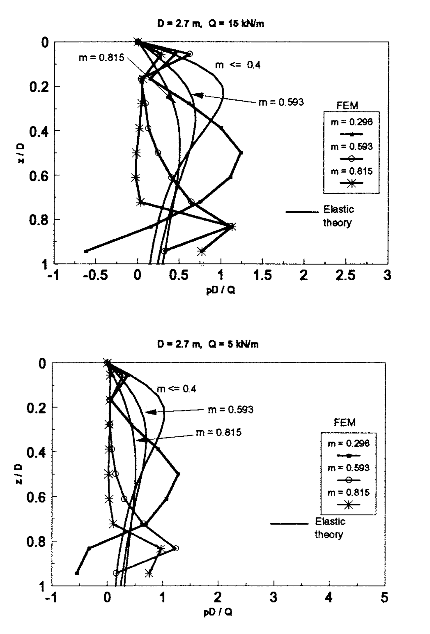
The above finite element results indicate that the lateral pressures acting on the wall stem are influenced by the magnitude of the line load and the point of application of the load. Also of interest is the increase in pressure (P) due to the application of the line load. This was obtained by subtracting the lateral pressures after the line load is applied from the lateral pressures at the completion of backfilling. Fig. 4 shows the non-dimensionalised plots of the results from Fig. 3 together with the results obtained using the theory of elasticity as outlined earlier in Fig. 1 (a). In some cases, negative values of p were computed close to the base of the wall stem. As mentioned previously, this was because the lateral pressures after the application of the line load were smaller than the pressures at the end of backfilling. A comparison of the results indicates wide variations in the pressure profiles predicted using the finite element method and from elastic theory. Similar differences were obtained for a 6 m high wall. For brevity, these plots have been omitted.
In elastic theory the backfill soil is assumed to possess infinite strength. As mentioned earlier, this implies that any combination of effective principal stress ratio is possible for the backfill soil. In reality, the effective principal stress ratios are limited to less than, or equal to, the value at which failure occurs. This accounts for the differences in the predictions between the finite element and elastic methods. For the retaining walls analysed, and for most gravity type retaining walls in general, at the completion of backfilling, most of the backfill soil in the vicinity of the wall back is in the active (failure) condition.
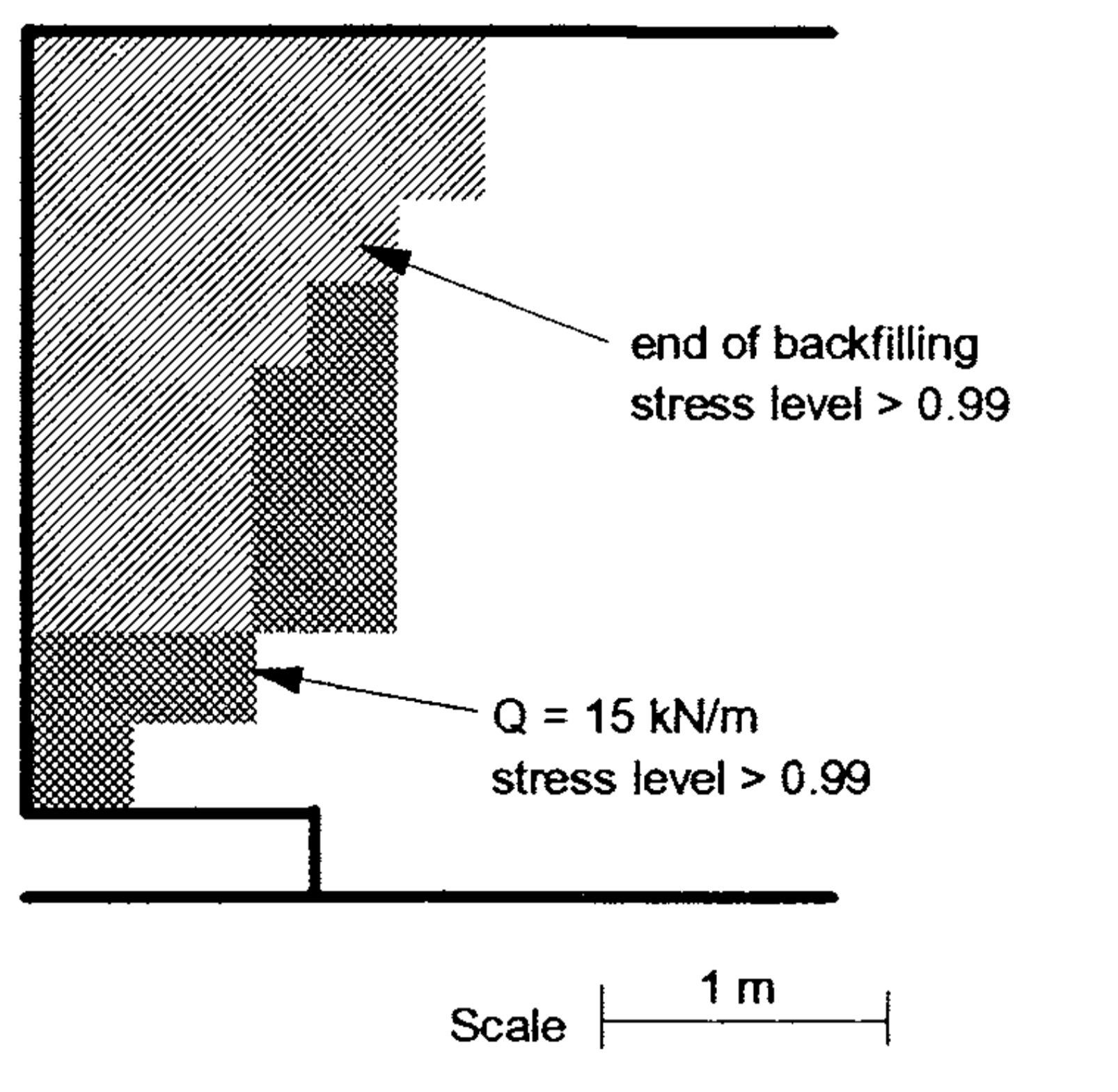
For example, Fig. 5 shows the plot at the completion of backfilling (CWLl) of the elements where the proportion of mobilised shear strength (stress level) is greater than 0.99, essentially defining the failure zone. With the application of the line load, the increase in the horizontal and vertical pressures for the elements in this ‘failed’ region were limited and resulted in a redistribution of the excess stresses to the elements immediately outside this region that were not at failure such as the soil directly above the wall heel. Consequently, this caused some of the elements directly above the wall heel to fail as shown in Fig. 5 for CWL2.
| Case | D(m) | Q(kN/m) | m = x/D |
|---|---|---|---|
| CWL2 | 2.7 | 15 | 0.296 |
| CWL2A | 5.4 | 15 | 0.296 |
| CWL5 | 2.7 | 5 | 0.296 |
| CWL3 | 2.7 | 15 | 0.593 |
| CWL3A | 5.4 | 15 | 0.593 |
| CWL6 | 2.7 | 5 | 0.593 |
| CWL4 | 2.7 | 15 | 0.815 |
| CWL4A | 5.4 | 15 | 0.815 |
| CWL7 | 2.7 | 5 | 0.815 |
6.2 Equivalent Horizontal Load
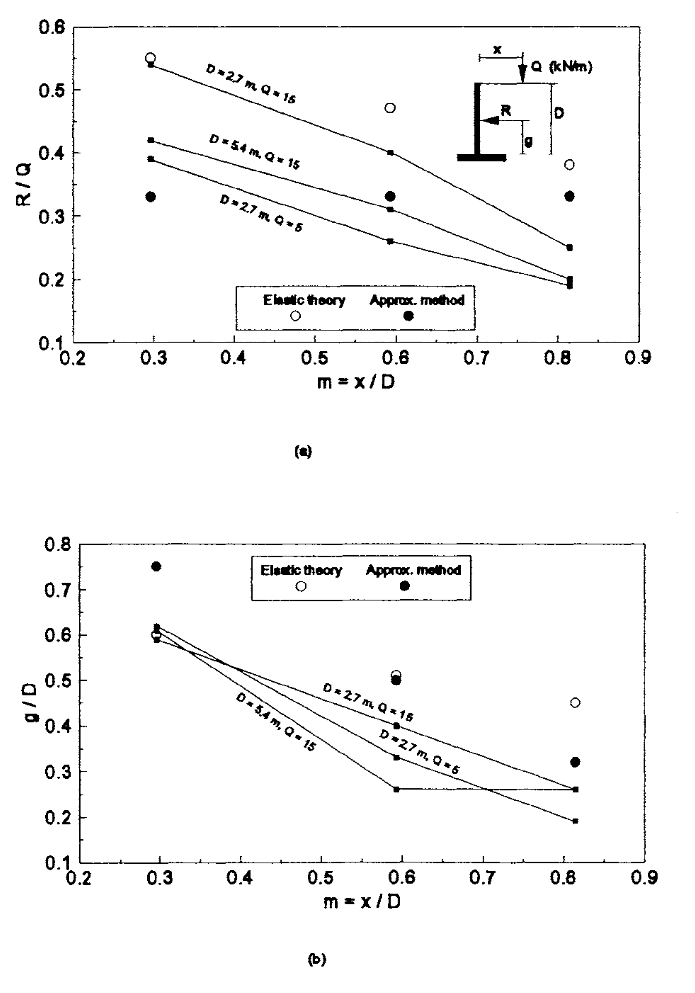
One simplistic procedure for considering the effects of a line load is to assume an equivalent horizontal load acting on the wall back. One such technique has been described earlier in Fig. 1 (b). In this section, the finite element predictions are compared with the results from this approximate method and from elastic theory. The normalised horizontal resultant force (R) and the line of action (g) of the resultant with respect to the base of the wall stem for the cases in Table 2 are plotted in Fig. 6.
From these results, the following conclusions can be made:
- For the finite element method, both R and g increased with increasing Q and decreasing m. Reducing Q to a third resulted in a 20% reduction of R. Rand g are also affected by the height of the wall stem D. Doubling the wall height resulted in a reduction of R of approximately one third.
- In the elastic method, Rand g also increased with increasing Q and decreasing m. However, R is independent of D. For example, a wall with D = 2.7 m and x = 1 m would give the same magnitude for R as a wall with D = 5.4 m and x = 2 m since m is the same in both cases. This appears unrealistic. It seems reasonable to expect that the latter should give a smaller R since the line load is further away from the wall stem. This is in fact confirmed from finite element analyses. The results however have been omitted from this paper as they did not reveal any further insights. The elastic method predictions for R were larger than the finite element predictions for all nine cases considered. These differences varied from about 3% to 60%. For the three cases where m = 0.296, the values of g obtained by both methods were in close agreement. In all the other cases, the elastic method predictions for g were at least 20% higher than the finite element predictions. This suggests that the elastic method can lead to very conservative estimates of the resultant.
- The approximate method appears unrealistic as it leads to values of R that are independent of m and D. The predictions for g were at least 20% higher than the finite element predictions. No distinct trend could be observed with regards to R although for m = 0.296, the approximate method resulted in smaller values than the finite element predictions.
7. Conclusions
The finite element method has been used to examine the behaviour of concrete cantilever retaining walls subjected to external line loads. The investigations indicate substantial variations in the lateral pressures obtained using the finite element method and conventional design techniques. The finite element allows for more realistic considerations of the soil-structure interaction, material nonlinearity and the construction sequence, and should lead to solutions that are closer to real situations than conventional design methods. Although experimental verification of the numerical findings is not available, these analyses should provide sufficient qualitative insights and guidelines for the development of improved design methods.
8. References
Civil Engineering Code Of Practice No.2 (1951). Earth Retaining Structures, BSI, London.
Clayton, C.RI. And Milititsky, J. (1986). Earth Pressure and Earth-Retaining Structure, Surrey University Press, Glasgow.
Clough, G.W. (1969). Finite Element Analyses of Soil-Structure Interaction in U-Frame Locks, thesis presented to the University of California, Berkeley, in partial fulfilment of the requirements for the degree of Doctor of Philosophy.
Clough, G.W. And Duncan, IM. (1971). Finite Element Analyses of Retaining Wall Behavior, Journal of the Soil Mechanics and Foundation Engineering Division, ASCE, Vol. 9, SMI2, pp. 1657-1673.
Coulomb, C.A. (1776). Essai sur une Application des regles des Maximums et Minimums a Quelques Problemes de Statique Relatifs a L’architecture, Memoirs Academie Royal des Sciences, Vol. 3, pp. 38.
Goh, A.T.C. (1993). Behavior of Cantilever Retaining Walls, Journal of the Geotechnical Engineering Division, ASCE (in print).
Goodman, RE., Taylor, RL. And Brekke, T.L. (1968). A Model for the Mechanics of Jointed Rock, Journal of the Soil Mechanics and Foundation Engineering Division, ASCE, Vol. 94, SM3, pp. 637-659.
Nayak, G.C. And Zienkiewicz, O.C. (1972). Elasto-Plastic Stress Analysis. A Generalisation of Various Constitutive Relations Including Strain-Softening, International Journal of Numerical Methods in Engineering, Vol. 5, No. 1, pp. 113-135.
Rankine, W.IM. (1857). On the Stability of Loose Earth, Philosophical Transactions of the Royal Society, Vol. 147, pp. 9-27.
Seed, RB. And Duncan, IM. (1986). FE Analyses : Compaction-Induced Stresses and Deformations, Journal of the Geotechnical Engineering Division, ASCE, Vol. 112, GTl, pp. 23-43.
Terzaghi, K. (1954). Anchored Bulkheads. Transactions ASCE, Vol. 119, pp. 1243-1280.
Terzaghi, K. And Peck, RB. (1948). Soil Mechanics in Engineering Practice. 1st edition. John Wiley, New York.