Capping of sediment deposition pits at Albert Park Lake, Melbourne, Australia
1. Introduction
Albert Park Lake is located 4 km south of the Melbourne Central Activities District. The lake, formed in the 1870’s from an existing lagoon system, is 48 Ha in area and is surrounded by 180 Ha of parklands and playing fields. With the passing of time, a number of stormwater drains which discharge into the lake had contributed to the accumulation of nutrient rich sediments. The depth of sediment varied from 0.3m to 1.0m with a total in-situ volume of 180,000 m³. The combination of shallow water (1.0-1.4m depth) and high nutrient load bad promoted the growth of weeds, algal blooms, damage to ecosystems and disruption to recreational activities on the lake.
Various options for addressing the problem including dredging or open-cut excavation and on-site or off-site disposal were considered. Removal by dredging and off-site disposal proved to be economically and practically unattractive.
Attention was focussed on on-site disposal. This involved the staged removal and burial of sediments in excavations within nominated sites within close proximity to the lake and utilizing sand from the excavations for subsequent capping of the deposition sites, landscaping works and creation of wetlands and storm water filtering systems within the lake.
Exceptionally wet weather from September to December 1992 resulted in sediments of extremely high moisture content prolonging the duration of the project.
2. Objectives
The major requirements of the project were:
The works were to proceed with minimal disruption to existing local bird and other wildlife populations and water sports. In order to meet this, the lake was to be drained, excavated and refilled in three sections between June and December 1992.
Material excavated from the lake was to be placed into excavations within two de-watered areas and stockpiled spoil was to be used to cover the sediments with up to 2.5m of sand
Stockpiled sands were also to be used for landscaping and other works within the lake and parkland environs.
3. Technical Considerations
The technical options of treating sediments prior to capping included mixing with sand where there was pressure to return areas to public use quickly. In less important areas, excavating pits, depositing sediments and lime stabilizing the upper 0.5m layer prior to capping was selected. It was recognised that there were levels of risk associated with each method, however, as they were considered feasible they were adopted for economical reasons.
The sediments were ultimately deposited into a total of 15 excavated pits of varying sizes, up to 50m by 100m by 5m depth within fenced and secured areas in the following manner:
| SEDIMENTS | MIXED WITH SAND | NO OF PITS |
|---|---|---|
| Pumped | No | 3 |
| Trucked | No | 9 |
| Trucked | Yes | 3 |
Lime stabilization was found to be ineffective. Mixing was found to be difficult to achieve by simple means in the field and early attempts to cap the sediment/sand mixture resulted in the mixture being heaved to levels above those desired, or being displaced by the capping sand into adjoining deposition pits.
At this time (December 1992) MP A Williams and Associates was engaged by Melbourne Water to investigate methods of capping the deposition pits based upon experience in the use of geotextiles to gain access onto tailings deposits.
4. Investigation and Design
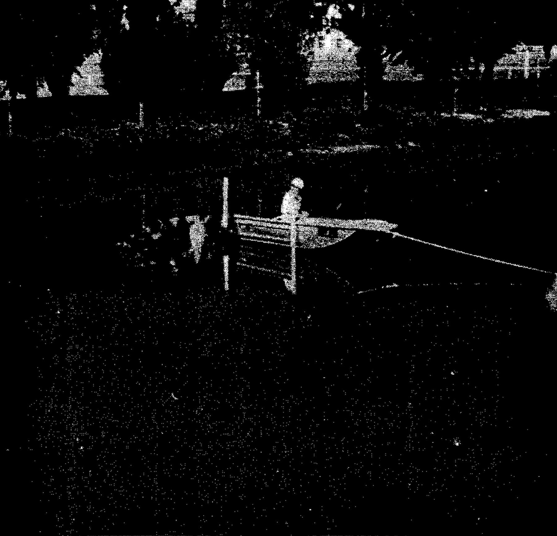
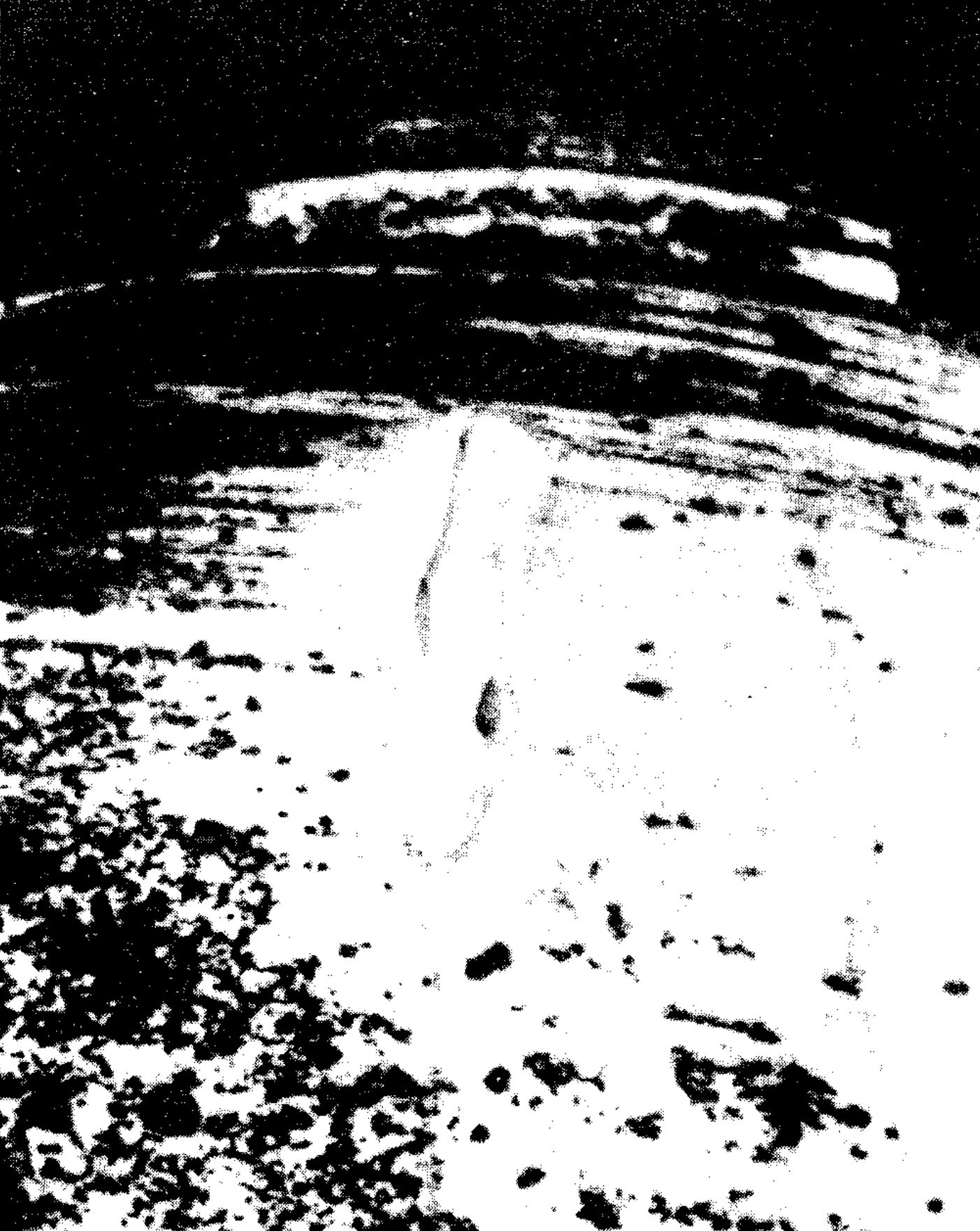
MPA Williams and Associates was originally commissioned to investigate one of each of the deposition pit types referred to above and to propose a method for trial capping of one pit. Initial investigations involved determination of in-situ undrained shear strength by shear vane. The shear vane also accurately determined the depth of sediment Assessing the shear strength of the sediments was a challenge in itself as they could not be walked upon. Access was gained by a combination of geotextile and plywood “stepping stones”. In the worst case, pumped sediments, access was only possible by boat. Figure 1 shows the surface condition of the weakest (pumped) sediment pit, where egress of consolidation water at the surface was still exceeding evaporation some 4 months after deposition. The surface condition of other ponds had the desiccated appearance featured in the foreground of Figure 1.
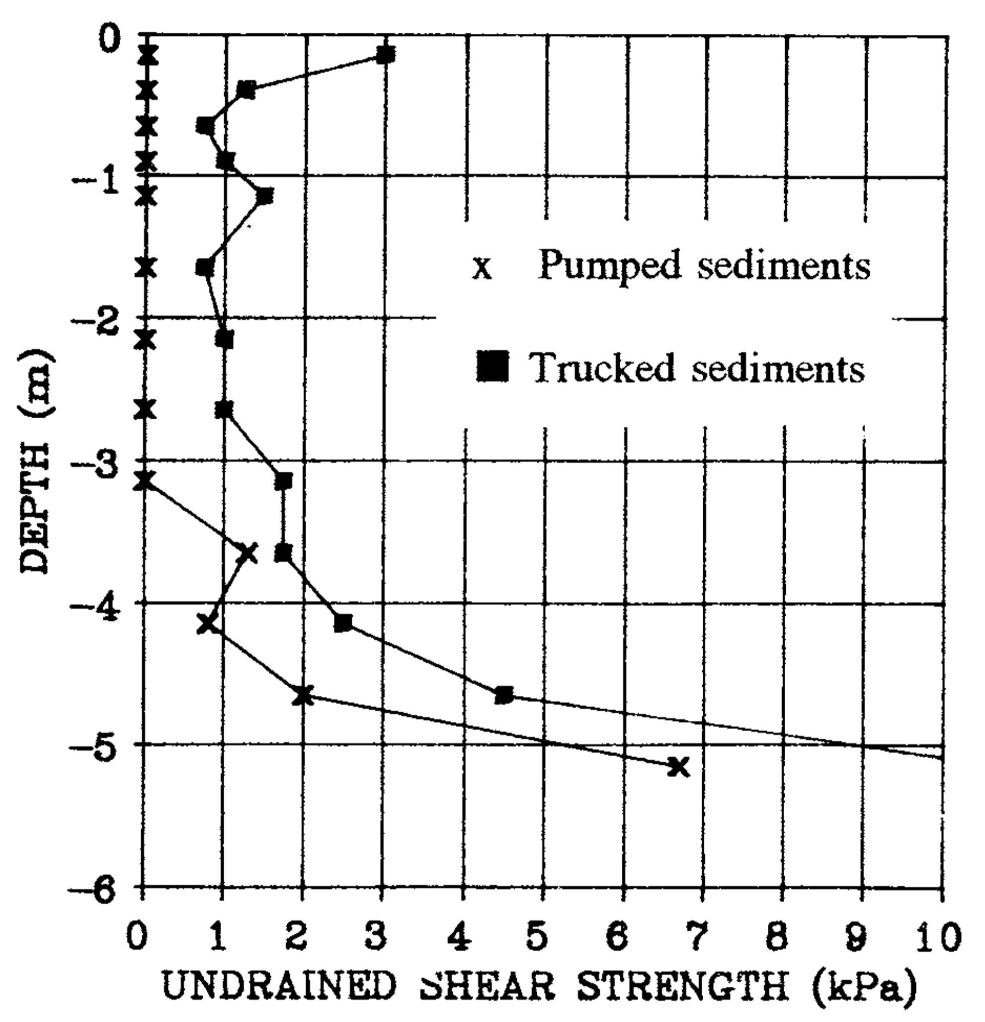
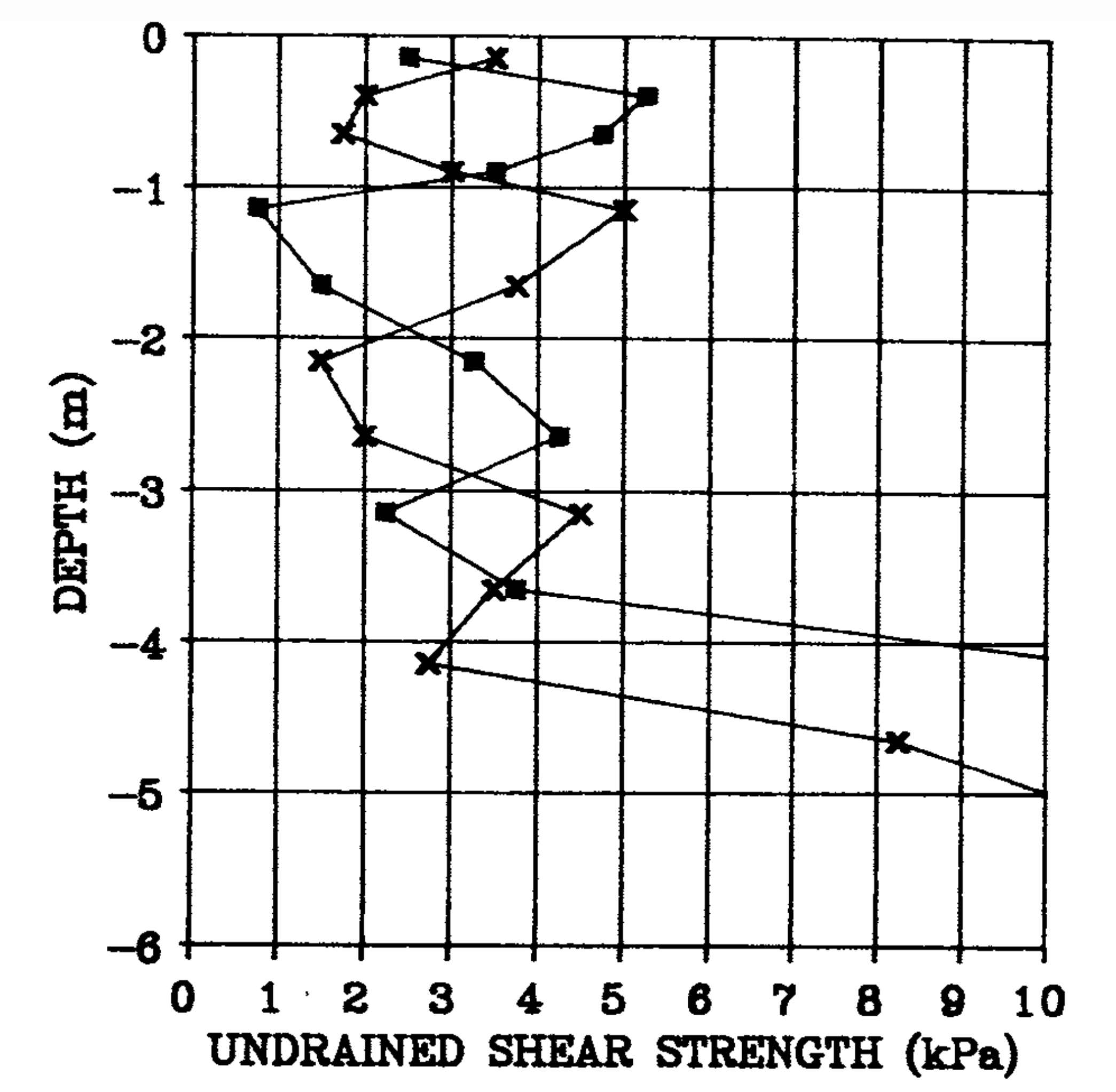
Typical undrained shear strength results (uncorrected for plasticity) for pumped and trucked sediments excavated early in the project are presented on Figure 2. Sediments excavated later in the project, seven pits in all, were slightly stiffer as a result of evaporation during excavation. The shear strength in these ponds was still, in the main, less than 4 kPa. A surface crust developed as time passed, however this was not sufficient to ensure trafficability to pedestrians. Typical shear strength profIles for these later ponds are presented on Figure 3.
Laboratory testing showed the sediments to be a high plasticity silty clay with a particle density of 2.57 t/m³, liquid limit 72-78% and plastic limit 30%. Moisture contents ranged from 58% to 158%. The potential capping material classified as fine to medium silty sand with fines content between 10 and 26% and coefficient of permeability m/s.
Previous experience in upstream raising of tailings dams and in successfully covering a tailings test pit approximately 20m by 20m with waste rock supported by geotextile led to the decision to pursue this option only. Other stabilisation techniques, including lime, cement and proprietary admixtures suffered from the same problem; how to mix the admixture in-situ when the sediments could not be trafficked or how to place the pre-mixed sediments evenly over the ponds at reasonable cost?
Experience indicated that a woven geotextile was preferable and that two layers placed at right angles and anchored with soil around the perimeter of the pond would be required. Stability and bearing capacity analyses including the weight of construction equipment showed that initial cover thicknesses of between 0.4 and 1m would be possible. The problem then became how to place the geotextile and cover? Placement of the geotextile was not such a problem as each layer could be pre-fabricated and placed by machine if necessary. A dragline was considered for cover placement but ruled out on the basis of cost. A technique proposed by Broms (1987) was ultimately considered wherein the cover placement proceeds by constructing “finger” bunds of limited height at uniform spacing across the ponds. Bund construction increases bearing capacity in two ways. Firstly there is an increase due to the tension in the fabric. Secondly, as construction proceeds, settlement occurs under the bunds and heave between them. This in effect creates a surcharge adjacent to the each bund and results in increased bearing capacity in accordance with the surcharge term in the classical Terzaghi bearing capacity equation. Once bund construction is complete the bunds are widened until the deposit is entirely covered.
Broms presents an analytical method and design charts for geotextile selection based upon bund width and height, bund spacing and tensile properties of the geotextile fabric. Broms also recommends the adoption of woven fabric and perimeter anchorage. Woven fabric is preferred because it is stiffer than non-woven fabric.
The adopted cover design for most of the deposition ponds consisted of two layers of 155 gm/m² woven polypropolene geotextile. Initially a drainage layer, Geonet TN1, supplied by Geofabrics Australia, was proposed between the two layers of fabric. This was subsequently omitted on the basis of cost. Each layer was sewn, and the two layers placed with the seams at right-angles. Perimeter anchorage consisted of a 1m high by 2m wide bund of sand placed around the edge of each pit. Initial stressing bunds were set at between 2 and 3m wide, 0.8 to 1m high and at 8m centres. Placement was proposed to be by a combination of “longreach” excavators and bobcats.
5. Construction and Performance
A trial initiated by Melbourne Water was carried out on one of the last pits to be filled. Construction was undertaken by John Holland Constructions, initially under the technical direction of MP A Williams and Associates.
This pit was one of the smallest in area and with shear strengths in the range 3-5 kPa was also one of the strongest. Melbourne Water chose Rheem Polytrac 155, solely on a cost basis. By the time construction commenced (March 1993) a surface crust, sufficiently strong to allow pedestrian access, had formed. This allowed the fabric to be placed by hand. Each successive panel was double sewn to produce a “J” seam. At the completion of placement each layer of fabric was tensioned as well as possible prior to placing the anchor bunds. Initial bund construction was carried out using a “longreach” excavator and bobcats. After initial scepticism, particularly on the part of the owner operators of the bobcats, the trial pit was successfully covered. The only departure from the method suggested by Broms was to simply fill in the gap between each bund from each side of the pit, rather than widening each one laterdlly. At completion a 20 tonne excavator was “walked” across one edge of the pit.
Melbourne Water made the decision to complete two more pits similar to the initial one and then move onto pits containing sediments of lower shear strength. The first of these lower strength pits contained sediments with shear strength in the range 1 to 2 kPa and again, by the time construction commenced, a surface crust sufficient to permit placement of the fabric by hand, had formed. This crust was approximately 75 to 100 mm thick. The same I construction sequence was followed and the crew had: gained experience allowing completion more quickly. Heave between, and settlement under the bunds increased significantly compared to the previous pits. It was found that the construction sequence had to be diligently arid methodically followed. Any attempt to cut corners by placing too much material too quickly resulted in unacceptable heave.
Using the adopted cover design and construction method, all of the pits which had been planned to be covered in the early 1993 construction season were successfully covered by June 1993.
Buoyed with the success of the method, and given the cost and difficulties involved in securing the one remaining pit from the public, it was decided to attempt to cover it. The remaining pit was the one containing pumped sediments as shown on Figure 1 and which effectively had zero shear strength to a depth of 3 metres. The pit dimensions are 50m by 100m.
Based on the tensile strength requirement of the geotextile and experience from the previous 13 pits, a third layer of geotextile was considered warranted. Because the surface of the pit was untrafficable the first layer of fabric was fully pre-fabricated and dragged over the pond surface by machinery operating from the perimeter. The seams were perpendicular to the long axis of the pit. Placement of the first layer of fabric was incomplete because adhesion between the fabric and largely fluid sediment threatened tearing of the fabric. The fabric ended some 25m short of the edge of the pit. Fabric was placed over the uncovered area with some difficulty by hand and was overlapped by at least 2m. Placement of the remaining fabric and anchor bunds proceeded without incident.
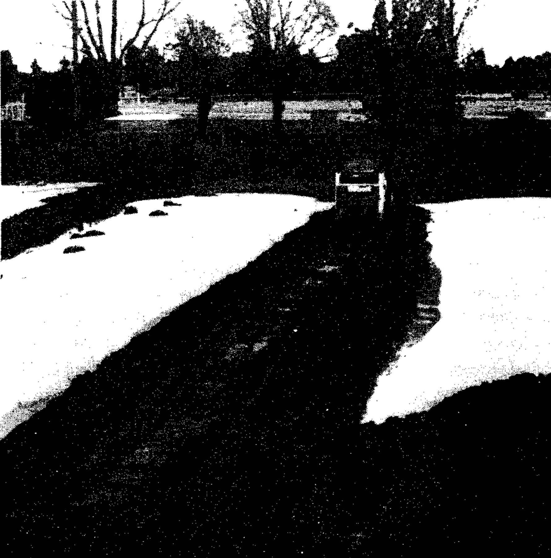
Placement of cover in this pit was complicated by the difficulty in ensuring site personnel strictly adhering to the specified work method, lack of technical supervision at the commencement and a fence abutting the pit on the western side. Construction of the initial stressing bunds was laborious because placement had to proceed from one side of the pit resulting in haul distances for the bobcats of up to 40m. This resulted in abrasion of the fabric due to repetitive loading and resulted in failure of the fabric at one location. Repair consisted of a double layer patch and was successful. Figure 4 shows construction of an initial bund. The bobcat is at the extreme end of its travel in a similar location to the boat shown on Figure 1. The deformed shape of the fabric is readily visible.
Because of the soft nature of this pit there was hesitation on the part of the operators and a tendency to place too much fill immediately adjacent to the edge of the pit. This resulted in overstressing of the fabric in several locations as shown on Figure 5. One rupture required significant remedial work.
Completion of this pit was further complicated by the nature of the cover material which, being the last available, was of poor quality with a high silt content and was very wet due to rain.
Covering of the pit proceeded under full time site supervision. The bearing capacity increase due to diligent placement of fill eventually resulted in the cover being capable of supporting a D3 size bulldozer. The cover thickness achieved was generally within the range of 0.6m to 1m, however, in several small areas near the centre, the cover thickness was as little as 0.1m. The cover thickness achieved was sufficient to render the pit safe to walk across and at this time work was suspended. The decision to suspend further work was in keeping with an overall decision to suspend landscaping work over winter. It is anticipated that consolidation of the sediments due to the fill placed will increase the shear strength to the point where a bulldozer up to D6 size will be able to complete the work late in 1993 or early in 1994.
6. Conclusion
This paper has demonstrated a method of utilizing geotextiles to assist in the covering of very soft clay sediment disposal pits. An analytical method proposed by Broms was used to determine the required tensile properties of the fabric. The method of placing the cover material was based upon a combination of recommendations by Broms, and previous experience in covering mine tailings.
Melbourne Water made a decision to adopt an innovative technique, one which, with the constructive input of John Holland site management and technical assistance by MP A Williams and Associates, resulted in timely completion of the project.
The major lesson to be learned from the project is that even minor departures from recommended procedures can result in unsatisfactory performance.
7. Reference
Broms, B. B., (1987) Stabilization of Very Soft Clay Using Geofabric. Geotextiles and Geomembranes, Jnl Int. Geotextile Soc., Vol. 5 No.1, Ed. T. S. Ingold, Elseveir.